Rozh -J) &ii Generator TechnicalData& OverhaulInstructions SERVICE MANUAL
FOREWORD This manual was compiled for dealers’ mechanics and includes descriptions on specifications, items, performance, structure, features, and maintenance procedures of the R1200 Generator. We ask each dealer to master the contents of this manual and provide users complete service after sales or proper guidance on how to use this generator.
CONTENTS Section 1. Title SPECIFICATIONS 1-1 1-2 FEATURES 3. COMPONENT 4. FUNCTION 5. 6. 7. 8. ........................................ IDENTlFlCATlON OF EACH COMPONENT ..................................... 6 7 7 9 Electronic ignition Mechanism ...................................... Description of Generating Operation .................................. 11 12 OF MAIN LIMITS OPERATIONS OF THE GENERATOR ............................. AC Output ...........................................
Title Section 9. DISASSEMBLY 9-1 9-2 9-3 9-4 9-5 10. PRECAUTIONS. ....................................... ............................................. Fire Prevention ............................................... Precautions for Exhaust Gases. ...................................... Other Precautions ............................................... 11. TROUBLESHOOTING 12. CRITERIA 13. WIRING 14. MAINTENANCE 14-1 14-2 14-3 14-4 14-5 14-6 14-7 ASSEMBLY Preparation and Remarks ...............
1. SPECIFICATIONS l-l ITEMS I Model Engine: Type Displacement 143 cc (8.73 cu. in.) Fuel tank capacity 3.5 lit. (0.93 U.S. gal.) Oil pan capacity I Ignition system Generator: Forced air-cooled, 4-stroke, side valve, gasoline engine I I I R1200 , 600 cc (1.28 U.S pints) I Starting system i Rated continuous operating hours I I I Solid state ignition Recoil starter I Approx.
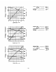
1-2 PERFORMANCE CURVES AC OUTPUT Power Factor . . . . . .. . . . . . . . . 1.0 1 ‘;; I -I0’ s z E IA z & 2 t z > ’ ’ I 1 1 1 1 1! output i Output Max. ............... 1000 w Rated ........... 800 W Frequency .................. 50 Hz Voltage ..................... 220 v 1000 50 800 I 600 z s P 230 400 2 220 210 200 49 240 0 1 2 3 4 5 n ” Current (A)- 52 51 Output Max. ................ 1000 W Rated ........... 800 W 50 Hz Frequency .................. 230 V Voltage ...................
;;; I 0” -IE ?T L 52 51 Output Max. ............... 1000 W Rated ........... 800 W Frequency .................. 50 Hz Voltage ..................... 110 v 1000 50 49 49 800 600 120 120-llOr 110 400 . 100 t z s 0. B 3 3 200 0 2 4 6 8 10 0 Current (A)- 62 1000 60 61 800 59 600 120 400 Output Max. ............... 1200 w Rated ........... 1000 W Frequency .................. 60 Hz 110 v Voltage ..................... f z s Q 5 0 110 100 200 0 2 4 6 8 10 Current (A)- Output Max.
G I 0” -1 f ltE z 28I s 62 ........... 1200 w Output Max. ...... 1000 W Rated ............. 60 Hz Frequency 12ov ............... Voltage 1000 61 800 60 59 600 400 130 120 110 t z s P s 0 200 0 2 4 6 8 10 0 Current (A) - DC Output DC output from this generator is rated especially for charging batteries. When the rated current (8.
2. FEATURES (1) Weight of this compact generator with excellent portability is 27.5 kg, which means that the generator is the lightest one in this class. (2) This generator with an excellent high performance engine and a large size 3.51i fuel tank can run continuously for about 4 hours (at the rated load of 50 Hz). (3) The operating system is concentrated on the front panel, which enables users to easily handle this generator.
3. COMPONENT IDENTIFICATION Engine Control Switch (CHOKE-RUN-STOP) DC Circuit Breaker \ / rter Recoil Starter Ground Terminal Air Cleaner Cover / Muffler / ler / crew ,,.,.,rnal) Fig.
4. 4-l FUNCTION OF EACH COMPONENT GENERATOR 4-l-l STATOR The stator consists of a laminated silicon steel sheet core, and a copper coil wound around the core with a lead wire from which AC and DC output are taken out. The copper wire coil consists of a main coil and a DC coil, and AC output is taken out from the main coil, while DC output is taken out from the DC coil.
4-l-4 AVR (Automatic Voltage Regulator) This is a device to automatically regulate voltage with an electronic circuit. I Fig. 4-14 4-l-5 CONTROL PANEL The control panel has a double receptacle with a ground terminal, and AC output is taken out with a male plug. DC current is taken out from the DC receptacle with a special plug. The voltmeter displays output voltage from the generator.
4-2 ENGINE 4-2-l CYLINDER AND CRANKCASE The cylinder and the crankcase of the engine are of a one-piece aluminum die-cast design. The specific iron cylinder is cast-fitted inside the cylinder. Both the intake and exhaust ports are positioned at the lateral side of the cylinder. These ports are also cast by using a mould with die-cast cores. The crankcase has its joint face located on the generator side, and it is of an assembly structure.
4-2-l 1 IGNITION SYSTEM The ignition system is based on a flywheel/magneto system and its ignition timing is set at 230C before top dead center. The magneto consists of a flywheel and an ignition coil. The flywheel (functioning also as a fan) is mounted on the crankshaft, while the ignition coil is mounted on the crankcase. 4-2-12 CARBURETOR The horizontal suction type carburetor employed here can provide excellent starting, good acceleration, low fuel consumption, and superior output.
5. 5-l DESCRIPTION ELECTRONIC OF MAIN OPERATIONS IGNITION MECHANISM The engine has a current chopping contact point-free ignition system in which a power transistor is used as a current control element. This system is called T.I.C. (Transistor Ignitor Circuit).
5-2 DESCRIPTION OF GENERATING OPERATION I------- = 8 P ‘3 ‘6 x L ---w_J , I I I Magneto F@. 5-2- I 5-2-l GENERATION OF NON-LOAD VOLTAGE When the generator starts turning, the permanent magneto incorporated in the flywheel in the engine side starts rotating, which generates voltage in the exciting coil. The voltage, rectified by the diodes in the AVR, causes the flow of the current @through the field coil wound around the rotor in the generator.
j-2-3 DC OUTPUT DC output is taken out from a part of the main coil and is fed to the diode stack (rectifier) where the output undergoes full-wave rectification and is then supplied to the load. The diode works to allow the current to flow in the direction @, but does not allow the current to flow in the direction @I, as shown in Fig. 5-2-3. Fig. 5-2-4 shows the DC output circuit of the generator. DC voltage is generated in the main coil.
6. OPERATIONAL LIMITS OF THE GENERATOR 6-1 AC OUTPUT Electric appliances normally have rating levels showing the rated voltage, frequency, power consumption (input power), and other things. The power consumption specified on such a label is required to drive the appliance. However, when an appliance is connected to the generator, the power factor and starting current should also be taken into account. 6-l-l NET RESISTANCE LOAD Incandescent lamps, electric heaters etc.
calculate the power consumption of the device involved. The calculated power consumption is adjusted depending on the type of the load, and according to paragraphs from (1) to (3). (Power consumption) = (Mechanical equivalent of a device) + (Efficiency) Efficiency Motors: 0.6 2. 0.8 Fluorescent lamps: 0.7 x0.8 Example: As for a 40 W fluorescent lamp with a lighting output of 40 W, and assuming that the power consumption of this lamp is 0.7, the power consumption can be calculated as follows: 40 + 0.
6-2 DC OUTitJT When the generator is employed to recharge batteries, attentions should be paid to the specific gravity of electrolyte in each battery. 6-2-l MEASUREMENT OF ELECTROLYTE’S SPECIFIC GRAVITY The specific gravity of an electrolyte varies according to temperature; so it is converted to one in case of 200C. s20 = St + 0.
64 WIRE LENGTH When long wires are used, resistance in each wire increases while voltage drop occurs. Consequently, the input voltage to an electric appliance declines, often damaging the appliance. The table below shows that the voltage decreases in 100 m wire with different cross sectional areas and varied resistances. No. of Cross sectional araa Alloweble current j conductor diameter I mm2 j 1 COIldUCtO~/ A j No./mm i ! Current Rasistanca a/lOOm 1 1A 3A 7 : 3010.18 ’ 2.477 2.
7. MEASURING PROCEDURES 7-1 METERS 7-l-l VOLTMETERS Both AC and DC voltmeters are necessary. Measurable range of the AC voltmeter is as follows. 0 to 15OV: For a voltmeter with an output voltage of 110 or 120V 0 to 300V: For a voltmeter with an output of 220, 230, or 240V Measurable range for the DC voltmeter is from 0 to 20V. For AC For DC Fig. 7-l- 1 7-l-2 AMMETER Both AC and DC ammeters are necessary.
7-l-4 CIRCUIT TESTER The circuit tester is used for measuring resistance and others. I Fig. 7-l-4 7-l-5 MEGGER TESTER This unit measures insulation resistance of the generator. Use one with voltage capacity of 5oov. Fig. 7-l-5 7-l-6 TACHOMETER Use the contact-less type tachometer. I 1 Fig.
7-2 MEASUREMENT OF AC OUTPUT +ii+~~ To an AC Receptacle Fig. 7-2 Measurement is executed with the circuit as shown in Fig. 7-2. An electric heater or an incandescent lamp with a power factor of 1.0 is suitable as a load for the generator. When the AC output measured at the rated load and rated speed is confirmed to be within the voltage range specified in the table below, the AC output is normal.
7-4-2 STATOR Measure the resistance between the red or white coupler leading from the stator and the core. If there is a section where insulation resistance is below 1MQ replace the part because it may cause insulation failure or such accidents as electric shock or leakage. I Fig. 74-2 7-4-3 ROTOR Measure the insulation resistance between either one of two slip rings of the rotor and the core.
8. FUNCTIONAL 8-1 CONTROL CHECK OF EACH COMPONENT PANEL 8-l-l AC RECEPTACLES Check continuity between the two terminals at the rear of the AC receptacles by using a circuit tester under the condition that the receptacle is mounted on the control panel. When continuity between the output terminals is confirmed with a wire connected across the terminals, and is not confirmed if the wire is removed, the AC receptacle is normal. Fig. 8-l-l (a) Fig.
8-l-4 VOLTMETER When AC voltage (1OOV)is loaded between the two terminals on the rear side of the voltmeter, and at the same time, the voltmeter shows the value, the voltmeter is normal. Fig. 8-l-4 8-2 DIODE STACK (RECTIFIER) (Orange) (Yellow) Fig 8-2-l 0 cl 0 0 - (White) (Brown) Fig. 8-2-2 Fis. 8-2-3 Circuit inside the diode stack is as shown in Fig. 8-2-l. Confirm continuity between each terminal by using a circuit tester as shown in Fig. 8-2-3.
83 AVR Whether the AVR is defective or normal can be determined by checking the appearance, by measuring the resistance between the lead lines with a circuit tester, or by practically loading it onto the generator. 8-3-l THE CASE WHERE DETERMINATION ACCORDING TO THE APPEARANCE IS POSSIBLE: If some electronic part of the AVR is burnt, has become black, or if epoxy resin on the surface has melted down, it can often be said that the AVR is defective.
84 STATOR Confirm the resistance between the coupler terminals with a circuit tester. Circuit Tester Red 3+-J a-@ White F&. 8-4 OB rown Orange Q @Black Green @ Coil name I Measurement location ’ Main coil DC coil Sub-coil 6P coupler Diode connector 6P coupler White @ - Wiring color Red @ 1 White - Yellow 50Hz - IOOV 0.951 0.32Q 60Hz - 1oov 0.6 0.23 50Hz - I IOV ! 60Hz - 1 IOV 1.2 0.44 0.9 0.32 White @ 4.452 3.6 I I 4.4 3.6 4.4 3.6 0.9 0.32 I 50Hz - 220V ! 5.
8-5 ROTOR 8-5-l MEASURE RESISTANCE IN THE FIELD COIL OF THE ROTOR WITH A CIRCUIT TESTER Resistance value El 10.7J-z Stlip Note 1: Measure the coil resistance between the two slip rings. Note 2: Sometimes the measured values do not match the values shown in the table above because of errors by the circuit tester, unevenness of the coil windings, or peripheral temperatuer. 8-5-2 CLEANING OF SLIP RING When the surface of the slip ring is smooth it is normal.
8-7 IGNITION COIL Measure resistance in the coil of the ignition coil unit with a circuit tester. ! Resistance 13K!G? i Note: 8-8 Measurement location ( I Measure the resistance between the black cord and the high tension cord. The measured value does not always match the values shown in the table above because of errors by the circuit tester, unevenness of coil winding, or peripheral temperature.
9. 9-l DISASSEMBLY PREPARATION AND ASSEMBLY AND REMARKS (1) Be sure to remember the locations of individual parts when disassembling the generator so that the generator can be reassembled correctly. Tie tags with the necessary information written in to facilitate easier and smoother reassembly. (2) For more convenience, group the related parts and store them in the same box. (3) To prevent bolts and nuts from being misplaced or installed incorrectly, temporarily at their original positions.
9-3 DISASSEMBLY I SEQUENCE to SequenceI, Part remove ! j 1 Description I 1 1Side cover ! (1) First remove the side ! cover by unscrewing I four M5 x 8 screws. I ! 2 ; Rear cover i (1) ! ! I i Remove the rear cover by unscrewing three MS x 8 , screws and two M 8 x 10 screws.
’ Part to Sequence ] remOve I 3 icontrol 1panel I I ! : I I(l) I I II I I I I Description Pull the knob of the control lever and remove the control panel by unscrewing four M5 x 8 screws.
Part to Sequence11 remove 4 ( Couplers 1and plugs , (Disconj nection) I i I I I j 1 Precautions Description , Pull the couplers i (1) Disconnect the (6P) ! while pushing the generator coupler from I retainer claws. the other (6P) coupler ’ extending from the 1 ! control panel. I , I / (2) Disconnect the (4P) coupler I of the AVR from the (4P) I coupler extending from the ; control panel. (3) Remove the plug for grounding. i i I I i I I i , I I !1 I Fig.
Part to Sequence I remove j 5 Description I I iFront cover (1) Remove the element cover by unscrewing ( the M6 x 12 screw. Precautions Necessary tools I 0 Driver 1 I I I(2) Remove the front cover by unscrewing three M5 x 8 screws. 1 ! @ Driver I M6x12 Screw ’ Front Cover / M5x8 Screw (3 PCS.) FJ$.
1 Part to ’ Sequencej remOve 6 Fuel pipe ‘and plug (Disconi nection) I Precautions Description (1) Remove the cap from the fuel strainer and take out the gasoline from inside the fuel tank. (2) With pliers, hold the fuel pipe clamp which is inserted in the fuel strainer and pull it forward to remove the fuel pipe from the strainer. I(3) Disconnect the plug receptacle of the engine from the plug of the AVR. j I ’ Pliers Be careful not to damage the fuel pipe.
Part to Sequence, remove I I 7 Fuel tank Ihandle Description (1) Remove the handle cover by unscrewing the two M3 x 10 screws. The fuel tank can be , @ Driver removed without I I disassembling the handle. (2) Pull out the breather pipe for air ventilation. : I (3) Remove the handle body by taking off the two M8 nuts. i Fuel tank 8 ! Necessary tools Precautions i (1) Remove the two M6 x 12 flange bolts clamping the I blower housing.
Part to Sequence remove 9 10 11 1 1 ’ , Precautions Description Necessary tools 13 m/m box Remove the bracket cover i spanner i from the generator by taking out the two M8 x 30 ’ 1 bolts. End cover /(l) Remove the end cover from. i @ Driver the generator by unscrew- i II I ing the four M5 x 10 screws.
I j Part to 1 Sequence I remOve 12 Precautions Description i (2) Remove the rear bracket, tapping it evenly with a plastic hammer. I (See Fig. g-3-10) Necessary tools 1 10 m/m box , spanner j (1) Loosen and take out the three M6 bracket bolts. ’ Rear ‘bracket I j a ’ I / (3) Remove the connector of ’ Be careful to make the d&e stack and then irregular wiring in , assembling. remove the lead from the I rear bracket clamp.
I I I I SequenceI rpearfito~~i 13 1Stator I I ! I c Precautions Description I Necessary tools (1) Pull away the stator cover. i (2) Pull away the stator from the front cover. If it is impossible, pull it away tapping outside the core with a plastic hammer. (See Fig. 9-3-12.) 1 1Never pat the wind- ’ plastic hammer / ing and the lead. I 1 ! ; I I I Stator cover Stator Fig. 9-3-l 1 F&.
Part to Sequence, remove 14 ‘Rotor ’ I I Description i (1) Insert a box spanner or a socket wrench between the through bolt and the rotor I I shaft, and hit it in a clockwise direction with a hammer to loosen the through bolt, thus keeping I a2 3 mm clearance between them. (See Fig. 9-3-14) ’ (2) Hit the through bolt head with a plastic hammer to I loosen the crank shaft and the rotor shaft taper. ! I Then remove the rotor. I (See Fig.
! Part to Sequencej remove 15 j Front i bracket I 1 I / ’ I I Description i I (1) Remove the front bracket, which is mounted on the I main bearing cover of the engine, by taking out four MS x 18 bolts. I Main Bearing Cover Front Bracket Fig.
I Part to i Sequence! remOve ;I 16 Recoil mstarter j(l) 11 Description I Remove the recoil starter by taking out the four M6 x 8 flange bolts. Precautions I RecoilvStarter Fig.
1 , j Part to Sequence1 remove 17 18 I Description Precautions j I I Blower i (1) Remove the blower housing The two flange 1housing bolts, taken out from the crank case by taking out the two M6 x 12 1when the fuel tank I I flange bolts. i is removed, are not / included. I I !Head cover I(l) Remove the head cover ‘& cylinder j from the cylinder head and baffle / the cylinder baffle from the cylinder by taking out the two M6 x 8 flange , bolts.
I !I Description I Precautions . @ Driver Air cleaner : (1) Remove the air cleaner body, elements, and element retainer from the cleaner body, by taking out I one M6 x 10 flange bolt. I Necessary tools i (2) Remove the air cleaner body from the carburetor by taking out the two M6 x 10 flange bolt. The air cleaner case !10 m/m box and the carburetor /spanner are clamped together. (3) Remove the gas exhaust pipe.
1 Partto j ISequence - remove ! 20 I Description Precautions j (1) Remove the muffler cover ’ from the muffler by taking ! out the three M6 x 8 flange bolts. I(1) Remove the muffler from the cylinder section of the crank case by taking out the two M8 nuts and Brace nuts one M6 x 12 bolt. I i Muffler Icover Necessary tools :lO m/m box i spanner i 21 Muffler I 112m/m box ’spanner 10 m/m box jspanner Muffler Cover nge Bolt (3 PCS.
Sequence11 Part to ’ Description remove : 23 Carburetor (1) Remove the carburetor from the cylinder section of the crankcase. 24 Starting (1) Remove the starting pully from the flywheel, by takPUllY j ing out one M4 nut. Insert a box spanner or socket wrench into the nuts of the flywheel and strongly hit it with a hammer, thus removing the nuts and the spring washer. I 25 Flywheel (1) Remove the flywheel from the crankshaft .
Sequence. 28 29 30 31 1 Part to 1 remOve I Ignition 1plug / Cylinder ,head I 1 Description I I (1) Remove the ignition plug from the cylinder head. j(1) Remove the cylinder head from the crankcase by taking out the eight M8 x 40 flange bolts. I(2) Remove the cylinder head gasket from the crankcase. I i (1) Remove the tappet cover , and the breather plate , from the crankcase by taking taking out the two ! M6 x 12 flange bolts. ! (2) Pull out the intake valve and the exhaust valve.
! Part to SequenceI remove I I 32 i Camshaft 33 Tappet Precautions Description I Set the crankshaft ! i ; on its side SO that j it will not fall and b i damage the tappets. (1) Pull the camshaft away from the crankcase. i (1) Remove the tappets from the crankcase. Intake Valve i ; ~~~a~s~~a~~ E:dthe I tappets to distini guish them from one 1 \ Valve Spring, i i L Camshaft Governor Gear, F&T.
r Wuence 34 Part to remOve , i Connecting i(l) :rod and :piston (2) ! 1 !(3) II I I 35 ‘Piston bc (1) !Piston ring : (2) 36 Crankshaft (1) :(2) 37 i Mount ;(l) I i Necessary tools Precautions Description Scrape off the carbon deposits from the cylinder and piston head. Then? in j order to remove the two bolts, open the bending section of the connecting rod lock washer. Remove the oil scraper, 1 lock washer, and connect- I ing rod cap from the crankshaft.
9-4 ASSEMBLY PROCEDURE n Precautions in assembly (1) Thoroughly clean each part. When cleaning, take special care with the piston, cylinder, crankshaft, connecting rod, and each bearing. (2) Be sure to completely scrape off th carbon deposits on the cylinder head and piston head. Also, thoroughly remove carbon deposits from each piston ring groove. (3) Check whether the lip of each oil seal is damaged or not, and if damaged, replace it with a new one.
HAssembly sequence and precautions 9-4-l CRANKSHAFT (1) Fit the crankshaft oil seal guide onto the crankshaft tip and assemble it with the crank case as shown in Fig. 9-4-l. Note: When the oil seal guide is not used, be careful not to damage the oil seal lip. .Crankshaft Mount the woodruff key (for the magneto). Dimentional tolerance of the crankpin. (2) (3) Crankcase Oil Seal Guide External Diameter 24~) Z-03; I I Fig.
9-4-2 PISTON AND PISTON RING (1) If a ring expander is not available, set the ring joint at the first land of the piston, as shown in Fig. 9-4-4. Then, open the joint wide so that the ring can be slid into the fegular groove. Note: Be careful not to twist or expand each ring too excessively. The oil ring is fitted onto the piston, followed by the second ring and top ring. Top Ring Second Ring Oil Ring F&. 9-43 Fig. 9-4-4 (2) The connecting rod is joined to the piston with the piston pin.
9-4-3 CONNECTING ROD (1) Turn the crankshaft as far as the bottom dead point. Then, set the connecting rod, gently striking the piston head until it touches the crankpin. (2) Set the connecting rod cap according to the rod guide mark. (3) Set the oil scraper in the magneto side. Note: Be sure to use a new lock washer. Bed the washer carefully and correctly. Note: When the connecting rod cap has been installed, manually turn the crankshaft to confirm that the connecting rod moves smoothly.
! Main Bearing Cover I i 1 Fi$. 94-7 F&. 948 * Fig. 9-4-9 shows an example of the methods to measure the side clearance of the crankshaft. In this case, it is measured by measuring the clearance between the processing face of the crankcase and adjusting color. As the packing is installed on the processing face of the crankcase, determine the clearance by taking into consideration the thickness of this packing which is 0.22 mm. Dial Gauge Processing Face of Crankcase / Fig.
WV&e h valve guide clearance Valve Face 3=53' / Valve Seat Valve Stem Valve Spring Spring Retainer Valve Guide Fig. 94 7 1 I A: Valve face angle B: Valve seat angle C: Valve guide inside diameter D: Valve stem outside diameter Clearance between the valve guide and valve stem (clearance between C and D) - Intake valve 1 6.5$1$;; Exhaust valve i -0.056 6*50- 0.078 Intake valve 0.025L - 0.062L Exhust valve 0.056L - O.
9-4-7 TAPPET ADJUSTMENT Set the tappet at the lowest point and push down the valve. Measure the clearance between the valve and the tappet stem, using a clearance gauge inserted into the clearance (See Fig. g-4-12). Note: When the engine is not running, the clearance between the valve and tappet stem must be in the range of 0.110.02. This holds true for both the intake valve and the exhaust valve. ~
9-4-10 IGNITION PLUG * Torque for the ignition plug: 230 ad250 kg-cm (As for a new one (head plug): 120 s 150 kg-cm) 9-4-11 IGNITION COIL, EXCITING COIL, FLYWHEEL AND STARTING PULLEY (a) Temporarily set the ignition coil and exciting coil in the crankcase and install the flywheel in the crankshaft. Clamp the starting pulley together with the flywheel. Note: Installment should be done after wiping away any oil from the crankshaft and taper section of the flywheel.
WHanging position of the governor spring Generally, the governor spring should be hung in 1 (See Fig. 9-4-15). (4) (5) Turn the speed control to the high speed side. Check to see that the carburetor throttle valve has been fully opened, and then lock it. Insert a driver into the governor shaft groove and turn it clockwise (until the governor shaft becomes unable to turn) to lock the governor shaft and the governor lever with the governor lever’s locking bolt.
9-4-14 MUFFLER AND MUFFLER COVER (1) Insert the gasket (exhaust) to the studs of the exhaust flange of the crankcase and then mount the muffler. Install the muffler by securing the muffler flange with two brass nuts and the muffler bracket with one M6 x 12 bolt. (2) Secure the muffler cover with three M6 x 8 flange bolts. Muffler
9-4-16 HEAD COVER AND BLOWER HOUSING (1) Set the head cover with the M6 x 8 flange bolts (at two places in the generator side). (2) Set the blower housing to the crankcase with M6 x 12 bolts. Note: The two M6 x 12 flange bolts for clamping the blower housing and head cover are used when the fuel tank is installed. Blower Housing M6x8 Flange Bolt (2 PCs.1 Head Cover I 2 Flange Bolt (2 PCs.1 Clamped with the fuel tank M6x12 Flange Bolt (2 PCS.) Fjg.
9-4-18 FRONT BRACKET Match the mounting hole of the front bracket with the inlet port of the engine’s main bearing cover. Torque for the front bracket: 120 0u140 kg-cm Note: Set the front bracket so that the cooling air outlet window of the generator is positioned in the upper side, and the slit section is positioned in the bottom side. 9-4-l 9 ROTOR Mount the rotor onto the taper section of the crankshaft and clamp it with through bolts. Note: Wipe off well oil or stains from the taper section.
9-4-20 REAR BRACKET AND STATOR Mount the diode stack on the rear bracket and combine them with the stator. Connect the connecting terminals according to the circuit chart. Note: See 8.2 “Diode stack” Fig. 94-27 9-4-21 STATOR (1) Holding the rear bracket and stator, fit them to the inlet port of the front bracket. Match the mounting hole of the rear bracket and that of the rotor bearing, and softly strike the outside periphery of the rear bracket with a plastic hammer.
9-4-22 BRASH HOLDER (1) Mount the brash holder base on the rear bracket with PI5 x 10 screws. (2) To install the brash holder put the M5 x 20 screw through the brash holder, and turn the screw, keeping it vertical against the slip ring. (See Fig. 9-4-23) Note: If the brash holder is inclined to the slip ring? the brash holder may break when the screw is clamped, or the brash itself may break when the engine is started.
9-4-23 END COVER Set the end cover on the rear bracket with four M5 x 10 screws. 9-4-24 BRACKET (COVER) Mount the bracket (cover) and the spacer on the rear cover and clamp them with MS x 30 bolts. /$a/” M5x20 Screw (2 PCS.) Brush Holder Rear Bracket Brush Holde\y , , Bracket p I d h \ M5xlO Screw (4 PCS.) M8x30 iiolt (2 PCS.
9-4-27 FUEL PIPE (CONNECTION) (1) Mount the fuel strainer on the front cover. Note: Mount the fuel strainer with the banjo outlet upward. (2) Insert the fuel pipe into the fuel inlet/outlet port of the fuel strainer and secure it with the clamp. 9-4-28 FRONT COVER AND ELEMENT COVER (1) Secure the front cover, on which the AVR and fuel strainer have been mounted, with three M5 x 8 screws. (2) Secure the element cover with M6 x 12 screws. Element Cover / M6x12 Screw Front Cover M5x8 Screw (3 PCS.
9-4-29 CONNECTION OF COUPLER AND PLUG (1) Connect th e coupler (6P) from the generator with the coupler thrusting from the control planel. (2) Connect the coupler (4P) thrusting from the AVR with the coupler (4P) thrusting from the control panel. (3) Connect the plug for grounding. 9-4-30 CONTROL PANEL (1) Thrust the control lever through the control panel and secure it with four M5 x 8 screws. (2) Set the knob on the control lever.
- 9-4-31 REAR COVER Secure the rear cover with three "Ix 8 screws and two &I8 x 10 screws. 9-4-32 SIDE COVER Secure the side cover with four M 5 x 8 screws. M8x10 Screw (2 pcs.) Rear Cover F&.
9-5 CARBURETOR 9-5-l FUNCTION AND STRUCTURE (1) Float System The float chamber is located directly under the carburetor. The float and the needle valves maintain a constant fuel level inside the float chamber while the engine is running. The fuel in the tank flows into the float chamber through the needle valve.
Schematic Diagram of the Fuel System r By-Pass Throttle ri Choke Pilot Jet Valve Main Nozzle Pilot Outlet Jet \ Float Fig.
9-5-2 DISASSEMBLY AND ASSEMBLY OF CARBURETOR The most common trouble with the carburetor, apart from mechanical ones, is failure to provide the correct air-fuel mixture. This is generally caused by blockage in the air and fuel channels or fuel level fluctuation. In order to maintain the carburetor in a normal operating condition, it is vital to keep the air and fuel channels always clean so that the fuel flows normally. Disassembling and assembling procedures are as shown below (Refer to Fig. 9-5-2).
I 25 3i 184 Fig.
10. SAFETY PRECAUTIONS 10-l FIRE PREVENTION (1) Keep the generator away from combustible materials during operations, or ground the generator by making use of its grounding terminal. Take special precautions towards flammable substances. (2) Do not run the generator in an inclined position. Avoid moving the generator while it is running. Otherwise, there is a risk of the generator falling or fuel leakage.
11. TROUBLESHOOTING Most generator troubles are caused by carelessness in routine handling, insufficient checks, or indifference to a slight trouble. Jn this section the causes and remedies to the major troubles concerning the generator are introduced. Generally speaking, the causes of the troubles are different case by case.
- II 1 Symptoms Parts A-l [ A-2 Starting failur; Starting failure Compression is insufficient Compression is nonexistent Intake/exhaust , or little valve I Adjust tappet clearance if the clearance is different from the standard value or replace 1 In case of sticking, supply lubricating oil onto value stem or replace the valve stem. Replace the piston ring when its operational limit is exceeded. Modify the cylinder bore when operational limit is exceeded.
.-. n I Symptoms A-4 Starting A-3 Starting failure Fuel tank is empty I failure Fuel tank, carbure- Fuel tank is empty ] Water or dust is mixed with the fuel Water or dust is mixed with the Fuel flows only a little, or does not Breather pipe (in the tank handle) Clogging of pipe Cock is closed Air stays in the Confirm condition of the cock Check the fuel pipe I Checking method Confirm fuel Checking criteria In case the fuel tank is empty, supply fuel.
qSymptoms .-- A-6 Starting failure The fuel does not flow into the combustion chamber although the fuel exists in the float chamber of the The fuel does not enter into the float chamber of the carburetor I r Fuel path (Carburetor) Packing (Carburetor) I -- Packing or clamping torque check - , ---- Checking criteria I 1. If the needle valve is contaminated with dust, etc., clean it. 2. In cast the valve does not work well, replace the valve.
q q q --.-.I I I Symptoms ---- Needle valve (Carburetor) Parts Abnormal operation Possible causes Checking method I I --.-- Float (Carburetor) 1 Float (Carburetor) Breather pipe (Air-vent) Oil level is abnormal (too high). Clogging of pipe _~ Breakage Check the needle valve check the float Confirm the oil level Check breather pipe 1. When dust, etc. is on the needle valve, clean it. 2. If the valve works abnormally, replace it. If the float is broken, replace it.
II Symptoms A-9 Starting failure A-10 Starting failure Sparks do not come out from the tip of the high voltage cord Sparks do not come out or are weak when the ignition plug is connected. il a a Ignition coil 1. Breaking of wire 2. Short circuit Air gap is too wide. I =I I Checking met hod Ignition coil Measure resistance valve between the terminals with a circuit tester Check the air gap L E Magneto (Flywheel) Demagnetization Exchange the magneto with a new one and restart it.
q Symptoms B-2 Abnormal B-l Abnormal running Overheating failure and knocking of the engine I Refer to A-l and A-2 (Clauses on compression failure) Cylinder, _. \ /’ r?J I 2 I muffler, 0 Carburetor Load Clogging of fuel path (Mixing ratio of air with fuel is too low) Overload I Checking method Check the cooling fin Check the cylinder head, muffler, and the exhaust hole. Check the carburetor Checking criteria In case the cooling fin is dirty, clean it.
El B-3 Abnormal Symptoms Fluctuation running of rpm Governor weight Governor sleeve -1. Governor spring is defective 2. Hanging position is not normal bluyylly “I l”Ul path (Mixing rati of air with fuel i! too low) 1. Abration 2. Abnormal operation I Check governor weight and gover- In case of fitting failure, correct it. rl Remedies hanging position is not normal. correct it. 2. In case the governor spring Is abnormal, replace it.
7 B-4 Abnormal Symptoms rpm of the engine does not increase I 0 Intake/exhaust valve Governor system Valve opening/ closing timing failure --‘I-’ Confirm mounting of the governor system Checking methoh In case of mounting failure, adjust it. Checking criteria El Carburetor Air cleaner I Mounting failure (Throttle valve does not work normally) Remedies running I Mixing ratio of air with fuel is not normal.
I I I B-5 Abnormal Symptoms running Missfire or explosion outside the tube I c I I Intake/exhaust valve Parts Carburetor r Checking criteria 1 I I Remedies I Ignition coil Fuel I I 1. Jets do not operate III Measure tappet clearance Check the jets Check the fuel If the clearance is different from the standard, adjus the clearance or rcplace the tappet Normal : 0.1 +O.O2mm 1. In case of jets failure, replace them. 2. In case of clamping failure, tighten it again.
u Symptoms ]I B-7 Abnormal (Air-fuel mixture I 1 1 Intake/exhaust valve intake valve, Valve seat Valve opening/ closing timing is not appropriate. Fitting of valve seat is insufficient, Checking criteria Measure tappet clearance If the clearance is different from the standard, adjust the clearance, or replace the tappet. Normal : 0.1 +O.O2mm il 2.
, B-8 Abnormal running Consumption rate of lubricating (White exhaust gas comes out) _-..Piston ring sured values on Checking criteria are not within In case of adherence, adjust or replace the piston ring In case the piston ring is built-in improperly, rearrange it. oil is too high I I I I Intake/exhaust valve guide Gas vent valve Engine oil If the clearance is not within the range of opera. tional limits, replace both the intake/exhaust valve and the guide.
I---B-9 Abnormal B-l 1 Abnormal running - running The lubricating oil becomes diluted and its consumption rate increases Engine noise is too loud I r Carburetor Engine oil Engine oil has not been changed periodically (Abrasion of rub hing section) n r Burning or breakage Mixing rate is too high md al the same time the cngino has tmen run 100 long under a light lord.
1 C-l No voltage is displayed on the voltmeter (1 I Symptoms I I Voltemeter AVR Brush l-7 I Slip ring J I contact surface of Voltmeter failure AVR failure 2. Abrasion of the Checking method Input AC voltage to terminals in the voltmeter side Measure resistance value between the terminals with a circuit tester (Measure with a 4P coupter) Lead line 1. Contamination of the brush’s contact surface 2. Abnormal abrasion of the slip ring 1.
C-2 No voltage is displayed on the voltmeter (2) Stator sub-coil 1. Disconnection 2. Short circuit 1. Disconnection 2. Short circuit I 1 Rotor Exciting coil 1. Disconnection 2. Short circuit 1. Disconnection 2. Short circuit -.---II I I I Checking method Measure resistance value between the terminals with a circuit tester (Measure with a 6P coupler) Checking criteria In case of * $1 . . . Disconnection In case of OS1 .. .
D-l No DC voltage is output Symptoms I I 2 I q q Parts Stator DC coil Possible causes 1. Disconnection 2. Short circuit Checking method I I Diode stack Lead line Confirm continuity between the terminals with a circuit tester In case of OQbl .. . Disconnection In case of Oil ...
L Symptoms -..Stator sub.coil q Possible causes I Ez I Checking method checking criteria Remedies I I Rotor Slip ring I I Short circuit of the coil I. Contamination of the brush’s contact surface 2. Abnormal abrasion of the brush’s contact surface Short circuit of the coil ---- Measure resistance between the terminals with a circuit tester (Measure with a 6P coupler) I / In case the measured resistance is lower than 15% of the standard, it suggests a short circuit.
q_- r-. Symptoms Parts low I I I Brush Ll ;I D-4 Voltage is abnormally Engine AVR I I I Fi I I c ’ AVR failure Fl I 1 Lead line I Breakage of lhe lead line I Checking method 1. Confirm condition of the slip ring’s contact surface 2. Measure length of the brush Measure resistance between the terminals with a circuit tester (Measure with a 4P coupler) Checking criteria 1. If contact surface of the slip ring is contaminated, clean it. 2.
CRITERIA 12. TABLE FOR ADJUSTMENT Items of adjustment Levelness of cylinder Criteira head Below 63Q Inside dia. Seat width of intake exhaust valves Cylinder ( Inside and Ring groove width ’ 62.980 ; Second Oil I ’ I I Description I j ’ r Clearance between ring and I ring groove +0.022 o 2.5 Center 6.650 ; Slide calipers and cutter I dia. gauge I Slide calipers Replacement i Slide calipers I 1 Replacement Replacement ! 2.15 2.* +0.035 0 ; I 2.
I Items of adjustment / Crankpin t Crankshaft I dia. outside ; Magneto side 1 : Crankshaft dia. journal ’ outside , Counterside 1 240 1 Magneto side Camshaft journal outside dia. I I Counterside I -0.037 -0.050 23.50 / 24.950 250 -0.003 -0.012 : 24.950 a.1 ! 24.7 ,50 -0.016 -0.027 ! 14.950 ,% -0.016 -0.027 14.956 Clearance between valve stem and valve guide I clearance I1 Tappet ; 6.350 Exhaust / Intake -0.
! Items Connecting Main bearing Cylinder of adjustment rod bolts kg-cm cover kg-cm head bolts bolts I Criteira 90-115 Limit of application ; kg-cm 805100 Description ) i Tools ! Remarks I ! kg-cm : 190-230 ! kg-cm j 230-250 / kg-cm i I Spark plug Air cleaner Governor I Rotor Muffler Front nuts level nuts bolts nuts cover bolts I Flywheel nuts I Rear bracket bolts kg-cm 70 -90 go-110 kgcm : kg-cm I 70 -90 kg-cm I ! 1202140 / kg-cm 1 600 -650 j kg- I 10
13. WIRING DIAGRAM 6P Coupler Generator 4P Coupler AC Circuit Breaker /ntroI \ Panel AC Receptacle / Engine Spark Plug ; i LT-Tw Yellow --mm I Magneto - I I I il Exciting Coil Ground Terminal Diode Stack Assy (Rectifier) I I Wire code I I em--I 0.75 mm2 I I 1.
14. MAINTENANCE The following standard maintenance procedures are necessary to ensure the generator’s normal performance under normal conditions. Therefore, it does not always mean that maintenance is not necessary until specified times. For instance, if the generator is operated in a dusty area, the air cleaner must be cleaned, not at the specified intervals, but rather daily.
144 CHECKS AND MAINTENANCE I FOR EVERY 200 HOURS (EVERY Checks and maintenance items I MONTH) Description (1) Drain oil from the crankcase and (1) Use of contaminated oil will cause rapid abrasion. replace with new oil (every 100 I hours) (2) E;p the fuel strainer and the fuel ! (2) and (3) a Engine troubles, including power output decline, will be caused. : (3) Regulate ignition plug clearance.
(5) Remove the ignition plug, and pour 5 - 10 cc oil into the ignition plug hole. Then quietly pull the startig nob of the recoil starter to distribute the oil to everywhere inside the cylinder, and then mount the ignition plug. (6) Check bolts and nuts for loosenessand tighten them more if necessary. (7) Set the engine switch at the “STOP” position. (8) Pull the starting nob of the recoil starter, and leave it at the position where some load is felt.
1 ISSUE EMD-GS0095 1 @FUJIHEAVY INDUSTRIES LTD. - INDUSTRIAL PRODUCTS DIV. 2ND Subaru Bldg.