
- Robin Generator Service Manual


5-2 DESCRIPTION OF GENERATING OPERATION
I-------
= ,
8 I
P
I
‘3
‘6
x I
L ---w_J
Magneto
F@. 5-2- I
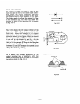
5-2-l GENERATION OF NON-LOAD VOLTAGE
When the generator starts turning, the permanent magneto incorporated in the flywheel in the
engine side starts rotating, which generates voltage in the exciting coil. The voltage, rectified
by the diodes in the AVR, causes the flow of the current @through the field coil wound around
the rotor in the generator. The rotor is then turned to an electromagnet by the current and at
the same time when it starts rotating, voltage is generated in the coils (main coil, sub-coil, and
DC coil) of the stator. -Then, the voltage generated in the sub-coil is rectified by the AVR, and
the current @ flows so that current in the field coil is increased. This increases magnetic
intensity to the rotor. Rated voltage is generated in the main coil and the DC coil by repeating
this operation.
5-2-2 VOLTAGE REGULATION UNDER LOAD
When a load is connected to an AC receptacle
and current is increased, output voltage fluc-
tuates and the voltage fluctuations in the case
where an AVR is in the circuit and in the case
where no AVR is in the circuit differ as shown
in Fig. 5-2-2. The AVR operates
as
follows.
When AC output is taken out, load is put on
the engine.
The AC voltage becomes lower
because rpm of the engine becomes fewer and
the voltage decreases on account of inner
resistance of the coil. The AVR detects the
voltage decrease and automatically increases
the current flowing through the field coil with
a thyrister inside the AVR.
As a result,
magnetic intensity to the rotor is increased
while the decreased voltage is raised again by
taking out loaded current, which in turn main-
tains the output voltage at a constant level.
When the AC output becomes lower the thyris-
ter provides reverse operation, and in this
case,
the voltage is also maintained at a
constant level.
Rated Level
Current (A)
F& 5-2-2
-12-