
- Robin Generator Service Manual


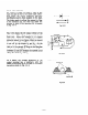


j-2-3 DC OUTPUT
DC output is taken out from a part of the
main coil and is fed to the diode stack (recti-
fier) where the output undergoes full-wave
rectification and is then supplied to the load.
The diode works to allow the current to flow
in the direction @,
but does not allow the
current to flow in the direction @I, as shown
in Fig. 5-2-3.
Fig 5-23
Fig. 5-2-4 shows the DC output circuit of the
generator.
DC voltage is generated in the
main coil. When the voltage in A is higher
than that in B, the current @ flows in the
direction shown in the figure, while no current
flows between CF and DE because the current
is cut off by the diodes G4 and G2. On the
contrary, when the voltage in B is higher than
that in A, the current @I flows in the direction
as shown in the figure. No current flows
between CD and EF because the current is cut
off by the diodes G1 and G3.
=
8
Fis. 5-24
As a result, the voltage generated at the
output terminal has a waveform with two
peaks in one cycle, as in the case of the output
waveform shown in Fig. 5-2-5.
Output Waveform
Current @
Curr&t @
F&. 5-2-5
- 13 -