
- Robin Generator Service Manual


i
1
Fi$. 94-7
F&. 948
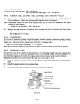
* Fig. 9-4-9 shows an example of the methods
to measure the side clearance of the crank-
shaft.
In this case, it is measured by
measuring the clearance between the pro-
cessing face of the crankcase and adjusting
color.
As the packing is installed on the
processing face of the crankcase, determine
the clearance by taking into consideration
the thickness of this packing which is 0.22
mm.
!
Main Bearing Cover
I
Dial Gauge
Processing Face
of Crankcase
/
Fig. 9-4-9
9-4-6 INTAKE VALVE AND EXHAUST VALVE
Scrape off deposits such as carbon gum from
the valves, valve seat, intake/exhaust ports,
and valve guide.
Note: If the valve face is worn, replace the
valve with a new one.
Valve Guide Puller
Note: If the clearance between the valve
guide and valve stem is too large, re-
place the valve guide with a new one
provided by the supplier.
While replace@, pull out the valve guide by
using a pull block and a pull bolt and then
pressure-fit the new one.
Fig. 9410
-52-