PARTS MANUAL Model R650 Generator
HOW TO USE .THIS PARTS CATALOG THEMODEL,SPECIFICATION,SPECIFICATIONNUMBERANDSERIALNUMBER OF THEGENERATORMUST BE GIVEN WHEN ORDERINGPARTS Specification and specification number are shown on the nameplate locatedon the rear cover. WRITEDOWNTHEMODEL, -SPECIFICATION, SPECIFICATIONNUMBER AND SERIAL NUMBER IN THE SPACES PROVIDED BELOW SO THAT ITWILLBE AVAILABLE TO YOU WHEN ORDERINGPARTS. FUJI HEAVY INDUSTRIESLTD. [ SPEC. NO. 1- t TOKYO JAPAN 1 J The serid.
2. Description of interchangeability and execution cohmns Example: Interchangeability column Example: Execution column 1 Items interchangeable between the new -0 10000 0 -I and old parts 1 Items not interchangeable between the new 1010;01For use for Serial No. up to 01 0000. X and old parts -Serial NO. I Items conditionally interchangeable between -For use for Serial No. from 010001. 1 y the new and old parts whicharesubject t o the description in the execution column.
CONTENTS BODY and GENERATOR PARTS .................................... Fig. 1 FUEL TANK . Fig. 2-2 CONTROL PANEL Fig 2-1 Fig 3-1 Fig.3-2 Fig.4 ................................ CONTROL PANEL (SPECIAL RECEPTACLE) . . . . . . . . . . . . . GENERATOR (For50/60 Hz) ......................... GENERATOR (For 60 Hz) . . . . . . . . . . . . . . . . . . . . . . . . . . . COVER . . . . . . . . . . . . . . . . . . . . . . . . . . . . . . . . . . . . . . . . 1 2 4 8 9 10 ENGINEPARTS . Fig. 5-2CRANKCASE ....
Fig. 1 FUEL TANK BODY and GENERATOR PARTS e l5 14 for Nu FILTER (NO.31) E:I 1 Description FUEL TANK. complete (Color: WHITE) 1 lnterclralngeabilitv Interchangeability FUEL TANK,complete (Color: BLACK) 2 FELT, tank 3 LABEL, caution 6 O-RING, tank 7 HANDLE, complete 8 ; BOLT, tank 9 ) BREATHER PIPE 1 0 . HANDLE COVER Part Number I1 ty. 358-61102-01 .I Q . 1 .
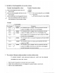
CONTROL PANEL Fig. 2-1 BODY and GENERATOR PARTS 32 1 ., lntercl 3ef I 40. - Description '1 CONTROL PANEL. complete (Mark.. X) Includes items 1 thru 61 For 50/60Hz-llOV '1 '1 '1 '1 . CONTROL PANEL, complete (Mark.. .W) Includes items 1 thru 61 For 60Hz-120V CONTROL PANEL, complete (Mark.. . Y ) Includes items 1 thru 61 For 50/60Hz-220V.
Fig. 2-1 CONTROL PANEL BODY and GENERATOR PARTS r Interchangeability lnterclharrgeability L 3ef do. Part Number ; Q t y Description j 3ef !xecution Description SO. 60 WIRE 11, complete 3584064308 1 61 WIRE 12, complete 38340751-O8! 1 58340640081 1 '70 WIRE HARNESS, complete Includes items 71 and 72 For oil sensor For 110V. l 2 0 V 32 VOLT METER For 220V. 240V 33 TAPPING SCREW 35841 1310 8 35841 132-08 3 4 ' LAMP 3834064508 1 For 110V.
Fig. 2-2 CONTROLPANEL(SPECIALRECEPTACLE) BODY and GENERATOR PARTS I 1 I I I !I - c tef Description SO. CONTROL PANEL,complete Includes items 1thru 64 50/60Hz-240V, For (Australia) '1 CONTROL PANEL, comDlete Includes items 1 thru 64 For 50160Hz-220V.240V. (England, BF) '1 ; CONTROL PANEL, complete i Includes items 1 thru 64 ' For 50160Hz-220V. (Switzerland) I '1 i i 1 I 3834065141 .i j I '1 I . j .. i I ! '1 ..
Fig. 2-2 CONTROLPANEL(SPECIALRECEPTACLE) BODY and GENERATOR PARTS I WlTH OIL SENSOR Interchangeability 3ef I Description 40. - 1i i Part Number JO'ty ! PLATE For England (684343) : 3584068408:. 3 SCREW I 358-406680a:4 4 AC RECEPTACLE For Germany 2 4 AC RECEPTACLE For Australia 4 AC RECEPTACLE For England (BF) 4 AC RECEPTACLE For Switzerland 4 AC RECEPTACLE For France 5 BRACKET For Australia 6 SCREW For Germany 6 SCREW For Australia . i 3584061408 1 . i .i .
GENERATOR (For 50/60 Fig. 3-1 Hz) BODY and GENERATOR PARTS 8 21 Description uo. *1 2 '3 ! I 1 Execution Pan Number IQ'ty Execution I ROTOR, complete Includes item 2 BALL BEARING STATOR, complete Includes items 4 thru 22 For 110V '3 STATOR, complete Includes items 4 thru22 For 220V '3 STATOR, complete Includes items 4 thru 22 For 240V 5 CONDENSER 6 BAND .
GENERATOR (For 60 Hz) Fig. 3-2 BODY and GENERATOR PARTS 22 2 \ 8 I nterch;angeability Interchangeability 3ef 40. - T Part NumberQ'ty -1 2 -3 ROTOR complete Includes item 2 383-21161 0 1 1 BALL BEARING : 358-21015481 1 STATOR, complete Includes.items 4 thru 22 For 120V Description Part Number IQ'tr I I 'i 383-22351011 ! .
.~ Fig. 4 COVER BODY and GENERATOR PARTS n 37 Interchangeability qef uo. 1 I Description ! Executton Part Number j Interchangeability lef ~ fI Description lo. - Part Number L’ti 383-9190743 1 1 - 1 ! FRONT COVER, complete : (Color: WHITE) 358-53001-31 1 FRONT COVER, complete (Color: BLACK) 358-53002-31 18 383-9190943 LABEL, spec.
. . Fig. 4 COVER BODY and GENERATOR PARTS Interct qeability i Description Part Number 41 MOUNT (A), complete 358-30101-1 1 42 BOLT and WASHER ASSEMBLY 001-14061-20 43 BOLT and WASHER ASSEMBLY 001-16051-00 44 MOUNT (8).
Fig. 5-1 CRANKCASE ENGINE PARTS 1 9 20 4 12 ',i 10 15 \ 16 22 Interchangeabili? ixecution Description 40. CRANKCASE, complete Includes items 2 thru 7 ief lo. - Description Pan Number I'ty - 230-1 0201-1 1 i 1 22 RUBBER PIPE (89x1 1@~48mrn) D85-1080040 1 2 VALVE GUIDE, over size 230-1420243 2 23 GASKET, tappet cover 230-1600643 1 3 STUD 010-5060160 2 24 BREATHER PLATE, complete 230-144014 1 1 4 STUD 01050601 -70.
Fig. 5-2 CRANKCASE (with 01L SENSOR) ENGINE PARTS 22 16 lnterclharlgeability - Ref uo.
~ . ~~ Fig. 5-2 CRANKCASE (with 01L SENSOR) ENGINE PARTS 16 ?ef lo. I Interchangeability Interchangeability Description 230-9900247 GASKET SET Includes items 9 , 1 5 , 1 8 , 2 3 , 25,27,29,32 Muffler-12 and Air Cleaner-7 I ji Part Number l u t y I . . j 1 I Execution lef I lo. : I Description j I Part Number IQ't) I" Execution , i i I I ! L 1 When ordering parts; Always give the Model, Specification and Serial Number of Generator.
Fig, 6 . CRANKSHAFT, PISTON and CAMSHAFT ENGINE PARTS . . 0 9ef Description UO. CRANKSHAFT, complete Includes item 2 -1 3 3 3 4 5 6 ' SPACER, t=0.8 I Part Number IQ'tyi ' 230-20301-01 I j 1 I :. 023-0200140 1 i Ii WOODRUFF KEY 1 10 i 11 12 12 12 13 PISTON PIN 14 CLIP I 1' 5 i CONNECTING ROD ASSEMBLY Includes items 16 and 17 i I 16 ROD LOCK WASHER 17 BOLT, connecting rod i IExecution ' :. ! ' : 023O2001-20 1 .00532042-011 1 .
- .. ~ GOVERNOR (For 50/60 Hz) Fig. 7-1 ENGINE PARTS 23 23 16 3 Interchangeability Description 1 , i GOVERNOR LEVER, complete 2 ; NUT 3 BOLT and WASHER I Part Number /O?y . ! '2304230141 1 I ~01880600-20! 1 ]001-14062-5011 ASSEMBLY 4 5 6 7 9 10 ! I I Execution ! I. ! i lo. lef I Description I 23 BOLT andWASHER . .
Fig. 7-2 GOVERNOR (For 60 Hz) ENGINE PARTS 3 Interchangeability qef I Description 40. ; I Part Number lClrty. I 1 GOVERNOR LEVER, complete 2 3 NUT BOLT and WASHER ASSEMBLY i 23042301-01I 1 I ! , . : . 101860600-20! 1 1001-14062-50i. 1 .. : ! 23042201-03' I : 4 GOVERNOR SHAFT 5 CLIP i 003-13050-00i 2 6 7 GOVERNOR ROD ' 23042701-01 j 1 1 I I Execution I 1 I .
Fig. 8 MUFFLER and FRONT HOUSING ENGINE PARTS 17 Interchangeability 7ef 30. 1 2 3 4 5 6 I Description i j FRONT HOUSING i CENTER BAFFLE , i I i 230-56002-03 ' Execution ?ef . Description 40. 19 1 ! 230-5300243 BOLT and WASHER ASSEMBLY i Part Number ! Q t y ! I I SCREW and WASHER ASSEMBLY 1 22 : SPARK PLUG CAP 065-50001-00 23 . SPARK 230-75101-13 BOLT and WASHER ASSEMBLY 21 004-3505140 1 001-1306260 1 4 ' 1 FLANGE BOLT 24 !CLAMP I . . i. i.
Fig. 9 CARBURETOR and AIRCLEANER ENGINE PARTS 20 10 11 13 35 14 15 Interchangeability 3ef Description - 40. i i ! 1 CLEANER CASE UNIT 2 CLEANER COVER 230-35501-23; 1 3 LABEL, air cleaner 073-20032-30 1 3 LABEL, aircleaner For France 073-20032-70j 1 4 RETAINER, element 230-36101-23i 1 5 ELEMENT,air cleaner 230-36102431 6 ELEMENT 2, air cleaner 230-36103-13 I 1 7 GASKET, air cleaner 8 BOLT, cleaner 230-35502-22i 1 .
Fig. 10 RECOILSTARTER ENGINE PARTS 12 I Interchangeability Description Part Number iQ'ty 3ECOILSTARTER ASSEMBLY Includes items 2 thru 11 230-5030200 SPIRALSPRING 230501 1608j 1 ?EEL 2305012008 3OPE ASSEMBLY Includes item 5 230-5010608 i 1 3ATCHET 2305012808 I 1 1 1 I I Execution Interchangeability qef 40.
Robin America, Inc. 940 Lively Blvd. Wood Dale, It 60191 Phone: 630-350-8200 Fax: 630-350-8212 e-mail: sales www.robinamerica. com @ robinamerica.