
Portable Generator User Manual


– 38 –
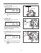
Top side of frame
Base plate
(Lower)
Sponge
(Base)
Brake
Battery
base
Wheel
Base plate
(Upper)
Shaft
5-4) REASSEMBLY PROCEDURES
5-4-2 SOUND INSULATOR
for SOUND-PROOF MODELS
(1) WHEELS
Inset the Shafts to the Base Plate (Lower) and
assemble the four Wheels to the Shafts.
(2) BRAKE
Assemble the Brake to the bottom of rear-left side of
the Base Plate (Lower).
M8 x 16mm Bolt : 1 pce.
(3) BASE PLATE
Attach the Sponge (Base) to the Base Plate (Lower).
Assemble the Base Plate (Lower) and Base Plate
(Upper) to the bottom of frame.
M8 x 16mm Bolt : 4 pcs.
(4) BATTERY BASE ( for electric start model only)
Assemble the Battery Base to the frame.
M6 x 12mm Flange bolt : 2 pcs.
NOTE : The mount rubbers are designed to isolate the
vibration most effectively by their original stiffness
and shape of rubber. Be sure to use the correct
mount rubbers attaching them to the correct position.
5-4-1 MOUNT RUBBERS
Attach the four Mount Rubbers to the frame. Insert the
locating tab of mount rubber into the locating hole of the
frame and fix it by tightening M8 flange nut.
M8 Flange nut : 4pcs.
5-4-3 FLYWHEEL
NOTE : Be sure to wipe off oil from the tapered portion
of the crankshaft and the hole of flywheel
before assembly.
Install the Flywheel onto the crankshaft and tighten the
Flywheel Nut using the special tool “FLYWHEEL
HOLDER” to hold the flywheel.
M19 Nut : 1pce. (EX17, 21)
Tightening torque : 59.0
-
64.0 N
・
m
590
-
640 kgf
・
cm
(43.5
-
47.2 ft
・
lbs)
Tightening torque : 10.0
-
12.0 N
・
m
100
-
120 kgf
・
cm
(7.4
-
8.7 ft
・
lbs)