- c5 -.-PARTS CATALOG Generafors Model RGD3700 c @ FUJIHEAVY INDUSTRIES LTD.
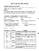
HOW TO USE THIS PARTS CATALOG 1. Reference numbers with an asterisk Reference numbers marked with an asterisk indicate that the particular available only as a complete set or assembly. Example part is : If the reference number is marked with an asterisk and the description of the part states that certain items are included, this means that those included items cannot be ordered separately and must be purchased as a complete assembly. 2.
. The contents of this parts catalog are subject to revision without notice. TO INSURE PROMPT AND ACCURATE SERVICE. ALSO THE FOLLOWING INFORMATION MUST BE GIVEN. 1. State exactly the quantity of each part and its part numbers. 2. Clearly state whether parts are to be shipped by express, freight or parcel post. 3. State the exact mailing address. CONTENTS Page GENERATOR FIG. 1 FIG. 2 PARTS GENERATOR .......................................................................
FIG.
FIG. 1 GENERATOR Ref. Parts No. I lnterdrarysabili ty Number Description Tt camp 1. ROTOR, BALL BEARING 385-50528-08 354-58204-08 21 2 Incld0s i&w 2 (8205-2RS) 1 1 c I Executiarl I I Ben orderiw I I I parts : Always give the k&l, Specification and Serial Nurber of Generator.
FIG.
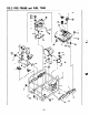
FIG. 2 PIPE FRAME and FUEL TANK ercrlption 385-58063-08 385-58582-08 31 385-59176-08 1 PIPE 1 SIDE [ LABEL FRAME.compl. PLATE.compl. (RGD3700) 1 41 011-00600-80 1 BOLT and 1 61 359-59933-08 1 FLANGE BOLT I 71 385-54826-08 I ENGINE BASE. I 81 228-15023-03 I VIBRATION I 91 002-27100-00 I STOPPER 11 1 001-11081-20 I 121I 001-86085-00 tI BOLT 131 002-37080-00 1 FLANGE 14 385-54827-08 15 I 385-57053-08 I BOLT I I 1 WASHER 20 I 064-13600-10 WASHER BOLT and 1.
FIG.
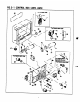
. -. FIG. 3-l z lo. 11 11 11 Parts CONTROL BOX (22OV, 24OV) Number 385-40606-08 lntardmunmhi Description CONTROL BOX I i t~v IJ’ t ASS’ Y For 220V 1 Includes items 2 thru 23, 25 thru 27, 33 thru 40 ad 46 385-40887-08 CONTROL BOX ASS’ Y For 5ONz-2WV, Electric starter type Includes iti 385-40688-08 CONTROL 1 2 thru 23,25,27 thru 30, 33 thru 43, 46, 47 BOX ASS’ Y 1 For 5Oik22OV, Oi 1 sensor type 11 lncludea itgls 385-40689-08 CONTROL 2 thru 23,25 thru 27.
FIG.
FIG.
FIG.
FIG. 3- 1 CONTROL BOX (22OV, 24OV) Ref. 1 Parts No. Description 0’ ty Execution I 41 42 I Number lnterchaageability 228-71920-01 001-11062-50 I REGULATOR, BOLT and For Efectric starter 43 44 385-47321-08 228-76001-01 CONNECTOR 01 L SENSOR, 45 001-11063-50 BOLT and For Electric Y ASS’ compl. WASHER starter type 1 2 typa camp WASHER For Electric starter type 1.
FIG.
FIG. 3- 2 CONTROL BOX (11 OV. 12OV) iz Parts lo. I1 El Number mbility Dercription BOX ty 385-40608-08 CONTROL 385-40693-08 Iacluder iteea 2 thru 23, 25 tbru 27, 33 thru 40 and 46 CONTROL BOX ASS’ Y For llOV, Electric ASS’ Y starter For 1lOV 1 1 type Includes itees 2 thru 23.25.27 thru 30. 33 thru 43. 46. 47 385-40694-08 CONTROL BOX ASS’ Y 1 For llOV, Oil senwx type Includes iteur 2 thru 23.
FIG.
. FIG. 3- 2 CONTROL BOX (11 OV, 12OV) Parts Number 385-41730-08 CONTROL PANEL For 60&120V, Electric +I II i t: A ASS’ starter type Y Execution Includes itewa 3 thru 23. 25. 27 and 26 385-41439-08 CONTROL PANEL A ASS’ i Y For 3OJk12OV, Oil aeuaor type Includes itewa 3 thru 23 aad 25 thru 37 385-41731-08 CONTROL PANEL A For 50&12OV, Electric ASS’ starter Y i type with Oil aeusor Inciudea itewa 3 thru 23.
FIG.
FIG. 3- 2 CONTROL BOX (1 lOV, 12OV) give the Specification -16- Int~whm~h~fit” Serial Auaber Generator.
FIG.
-. FIG. 3- 3 CONTROL BOX (11 OV/ 22OVl Ref. Parts Number Description Q’t NO.
FIG.
FIG.3-3 Ref. NO. c CONTROL BOX (llOW22OV) Parts Number Interchangeability Description 1’ t) 20 21 356-49907-08 353-49902-08 SCREW 1 NUT 1 22 332-00050-08 SPRING WASHER 353-49903-08 1 WASHER 2 1 24 356-45612-08 SWITCH.
FIG. 3- 4 CONTROL BOX (U.K., 50Hz- 11 OV/ 22OW BS) I For Oil sensor type 0-l ‘. I .
FIG. 3-4 Ref No. Parts CONTROL BOX (U.K., 50Hz- llOV/22OV, Number BS) Inter& Description Execution I *l 385-40702-08 CONTROL *I 385-40703-08 Includes itews 2 thru 27.
FIG. 3- 4 CONTROL BOX (U.K.
FIG. 3- 4 CONTROL BOX (UK., SOHz- 1 lUv/220v, Ref. Parts No. r\ Number Bs) Interchaageability Description 201 358-49907-08 1 SCREW 211 353-49902-08 1 NUT 221 332-00050-08 1 SPRING 231 353-49903-08 1 WASHER 241 355-45613-08 1 SWITCH.
FIG.
FIG. 3- 5 CONTROL BOX (GERMANY. 5UHz- 22OV) Ref. No.
FIG.
. __-. -._ FIG. 3- 5 CONTROL BOX (GERMANY, 50Hz- 22OV) II Ref. No.
FIG.
FIG. 3- 6 CONTROL BOX (50Hr 22OV. WITH SPECIAL RECEPTACLE) Interchang&ility Ref. Parts No.
FIG.
FIG.
FIG.
. - FIG. 3- 7 CONTROL BOX (SWITZERLAND, 50tiz- 22OV) Ref. No. *l *l Parts Number Description CONTROL 385-40719-08 Includes iters 2 thru 2’7, 33 thru 40 and 48 CONTROL BOX ASS’ Y Includes i-s *l 385-40720-08 CONTROL Includes iti 81 0’ ty 385-40718-08 For Electric 385-40721-08 CONTROL For Electric BOX starter ASS’ Intedangeability Y 1 1 type 2 thru 25.
FIG.
- --- , I= FIG. 3- 7 CONTROL BOX WWTZERLANO, 1251 363-49091-08 1 LABEL(DC 1261 389-47552-08 i GROMMET 1 !Z’7lI 355-57509-08 281 066-00002-50 I GROMMET I 1 SWITCH ’ 29 385-45517-08 FUSE 30 385-45518-08 FUSE 32 351-45302-08 LAMP, I I I BATTERY HOLDER (15A) For Electric starter I 1 starter type _.
FIG.
FIG. 3- 8 CONTROL BOX (AUSTRALIA, !5Of=lz-24OV) Interchauseabilitv Description CONTROL BOX ASS’ Y Includes item 2 thru 27, 33 thru 46 and 46 CONTROL BOX ASS’ Y For Electric starter type 81 385-40724-08 Includes items 2 thru 25.27 thru 30. 33 thru 43, 48 and 47 CONTROL BOX ASS’ Y For Oil sensor type Includes items 2 thru 27.
FIG.
FIG. 3- 8 CONTROL BOX (AUSTRALIA. Ref. No.
FIG. 3- 9 CONTROL BOX (FRANCE.
FIG. 3- 9 CONTROL BOX (FRANCE. ‘BOHz- 22OV) Ref. No.
FIG.
FIG. 3 - 9 CONTROL BOX (FRANCE. 50Hz- 22OV) --w-m-. Ref. No.
FIG.
FIG. 4 RECOIL STARTER Ref. Parts No. *1 Intexdangdili Number 228-50110-00 Description RECOIL STARTER P’ ty ASS’ Y Executiw 1 I Includes iters 2 thru 11 f 21 1 3 106-50116-08 107-50121-08 SPIRAL REEL SPRING 1 228-50110-08 STATER ROPE 5 206-50101-08 STATER KNOB, 6 106-50128-18 RATCHET 7 106-50132-08 FRICTION 106-50137-18 RETURN 106-50144-18 FRICTION 8 I 01 10 106-50185-18 THRUST 11 106-50186-08 CLIP 12 011-00600-10 FLANGE 1 compl. 4 1 camp 1 1.
FIG.
FIG. 5 CRANKCASE Ref. No. I *l Parts lnter&aage&ility Number Description 228-10110-01 CRANKCASE, camp For Recoil starter 3’ ty 1. Execution 1 type Includes iteas 2 thru 7 aad 51 81 228-10112-01 CRANKCASE, For Electric camp starter 1. 1 type Includes iteas 2 thru 7. 8 and 51 CRANKCASE, compl. I ‘I For Oil seasor type I I Includes itews 2 thru 8 camp CRANKCASE, For Electric starter 1.
FIG.
_ . _- -. FIG. 5 CRANKCASE Description I -r 28 021-32000-10 GASKET 30 31 009-02120-00 003-70120-00 FILLER GASKET, 32 228-64301-00 OIL 1 -1 aluminum FILTER 33 024-03000-10 ‘0” 34 35 228-63601-01 001-13088-50 OIL BOLT 38 001-13086-50 BOLT and 37 38 001-13082-00 BOLT and 001-13084-00 BOLT 39 001-13085-50 BOLT 42 980-05060-10 BOLT 43 014-90600-70 ADJUSTING 44 I 002-18060-00 451 041-12200-10 I I I 1 ASS’Y 1 RING GAUGE. compl.
FIG.
FIG. 6 CYLINDER and CYLINDER HEAD lnt*rchanaprhi I Ref. No. Parts Number 1 228-12401-12 2 228-15011-03 Description CYLINDER ‘0” RING, . . -* R’ty UNIT 1 cylinder 1 3 228-15012-13 SPACER, cylinder (t-0. 1) 1 3 228-15013-13 SPACER, cylinder (t-0. 2) 1 228-13110-01 CYLINDER HEAD, Includes i teas 5 thru 8 228-14202-03 VALVE =4 5 comp.1. GUIDE 1 2 ker Whenordering parts : Always give the Hodel, Specification cover and Serial Numberof Generator.
.FIG .-. 6- CYLINDER -. --.- ---- h and CYLINDER HEAD _...
FtG. 6 CYLINDER and CYLINDER HEAD 002-18060-00 1 4 1 NUT Whenordering parts : Always give tbe Hodel. Specification Interchangeability and Serial Wurber of Generator.
FIG.
.. _,-. FIG. 7 CRANKSHAFT Ref. Parts No. and PISTON Number Interc@geability Description Yt 1 228-23401-23 PISTON, S. T. 1 228-23402-23 PISTON, over size 0. 25mm 1 1 228-23403-23 PISTON, over size 0. 5mm 1 228-23501-07 PISTON RING SET, S. T. D 1 8 D Execution 1 t- I-- Includes itees 2 thru 4 * 228-23502-07 PISTON I *I 1 228-23503-07 RING SET, over size 0.
FIG.
FIG. 8 CAMSHAFT Parts No. *1 and GOVERNOR Number Description 228-31604-00 I 81 I 228-31604-01 82 3 CAMSHAFT ASS* Y Includea iteas 2, 3 and 4 thru 6 CAMSHAFT, camp 228-33222-01 CAMSHAFT 005-32042-01 WOODRUFF GEAR, KEY 1 I I 1. Includes i teas 4 thru 6 c omp 1. Include8 item 8 1 1 I L- c.
FIG.
FIG.
FIG. 9 FUEL INJECTION PUMP and NOZZLE 1 -33 . ;.._ :.
-. FIG. 9 FUEL INJECTION PUMP and NOZZLE Ref. No.
FIG.
FIG. 10 FUEL FllTER f Ref. Parts No. Number Description 228-62106-00 81 I 81 FUEL 1 228-62109-08 91 228-62110-08 FILTER !Y ty ASS’ Y Inclndes itees 1 thru 11 1 ‘0” 1 I I I 11 RING 1 ELEMENT 1 BOLT and WASHER I 11 8141 228-62629-01 1 FUEL PIPE 29. I ‘I I I compl. Includes items 15 thrn 17 and 21 I’I I 15 228-65007-03 BANJO 18 085-10400-00 RUBBER PIPE (4. 5#X9+X270mm) 1 17 085-10400-00 RUBBER PIPE (4.
FIG.
FIG. 11 AIR CLEANER, MUFFLER and CYLINDER SAFFLE Ref. Parts No. 1.11 231-32601-00 *3 4 5 Number I 1 AIR 228-32600-08 ELEMENT, PACKING 228-32710-08 228-92302-03 I OIL 228-92303-03 LABEL, 228-35009-03 CAP, 101 980-05060-10 compl.
FIG- 12 MUFFLER (SPECIAL TYPE) FOR LOW NOISE TYPE 12 FOR WITH SPARK ARRESTER - 67 -
FIG. 12 MUFFLER (SPECIAL TYPE) escrlption 1 228-30302-01 MUFFLER, compl. 2 2 228-34260-01 228-34201-11 MUFFLER MUFFLER COVER, COVER, 31 228-35019-01 1 MUFFLER 1 41 228-37001-01 I TAIL PIPE, 41 228-37010-01 1 TAIL PIPE,compl. For Spark arrester 51 228-37201-11 I BAND, compl. For Lorr noise I 61 228-37301-01 1 SPARK 1 GASKET,tail compl.
FIG.
FIG. 13 STARTING MOTOR Ref. Parts No. *l Number Description 210-70502-10 I I 1 STARTING 210-70532-08 2 3 210-70533-08 210-70534-08 *4 I210-70535-08 ASS’ Y I I Includes i teas 1 thru ~6. 29 and 30 ARMATURE THRUST PINION 1 FIELD 5 210-70508-08 POLE 6 210-70539-08 BRUSH 210-70538-08 BRUSH *7 MOTOR ASS’ Y 1 WASHER KIT STOPPER SET COIL ASS’Y CORE SET 1 1 Includes iteas 5 and 6 SCREW 1 1 4 (+) 2 HOLDER ASS’ Y 1 Includes itens 8 and 9 8 r.
FIG.
FIG. 14 ACCESSORIES Part8 1 I Number I I Whenordering parts ; Always give the Hakl, Specification and Serial Numberof Generator.
FIG.
FIG. 15 WHEEL, HANDLE and HANGER Ref. No. 1 I6 7 Parts Number Description 1’ ty 1 SHAFT. comn _ 1. 450-00009-90 LARGE WHEEL 385-56562-08 HANDLE 1 Includes itea 5 1 385-56563-08 HANDLE 2 Includes item 5 1 385-56517-08 CLIP 380-56548-08 385-56564-08 385-54387-08 BRACKET, HANDLE 1 WASHER I 385-54388-08 1 COTTER I 385-54457-08 SHAFT, 385-54389-08 WHEEL I compl.
. I
c c
@FUJIHEAVY INDUSTRIES LTD. - INDUSTRIAL PRODUCTS DIV. Subaru Bldg.