3 Year Limited Engine Warranty 6. Engine tune-ups and normal maintenance service including, but not limited to, valve adjustment, normal replacement of service items, fuel and lubricating oil, etc. (Special Term for Welder Application) 7. Any engine which has been subject to negligence, misuse, accident, misapplication or over-speeding. 8. Any engine that has been installed, repaired, or altered by anyone in a manner which in Robin’s sole judgment adversely affects its performance or reliability. 9.
Safety Precautions Before operating the engine, read this manual and become familiar with it and the equipment. Safe and efficient operation can be achieved only if the equipment is properly operated and maintained. The following symbols, found throughout this manual, alert you to potentially dangerous conditions to the operator, service personnel, or the equipment. ! DANGER This symbol warns of immediate hazards which will result in severe personal injury or death.
moving parts, etc. • Used engine oils have been identified by some state and federal agencies as causing cancer or reproductive toxicity. When checking or changing engine oil, take care not to ingest, breathe the fumes, or contact used oil. • Do not work on this equipment when mentally or physically fatigued, or after consuming any alcohol or drug that makes the operation of equipment unsafe. BATTERIES • Before starting work on the engine, disconnect batteries to prevent inadvertent starting of the engine.
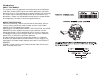
Introduction ABOUT THIS MANUAL This manual covers the operation and maintenance of the horizontalshaft Robin Subaru EH65 engines for welder applications (OHV220 Performer Series). Each operator of the power equipment should study this engine manual carefully and observe all of its instructions and precautions. Proper use and periodic maintenance are responsibilities of the operator(s) and are essential for top performance.
Description Specifications FEATURES • Overhead valve arrangement enables high power, and low fuel and oil consumption • V-Twin, four stroke design • Air-cooled and gasoline fueled • The light weight and compact design makes it easy to install and utilize for many applications. • A steel crankshaft and high-load bearing offer durability • Pressure lubrication system and large capacity air cleaner enhance reliability of the engine.
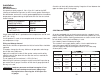
Installation LOCATING Locate the engine at least 1 meter (3.0 ft) away from buildings or other structures. Provide proper exhaust routing. Refer to EXHAUST SYSTEM below. Do not use the engine near flammables or other hazardous materials such as trash, rags, lubricants, or explosives. When determining the mounting location, make sure of the following: • Gas and oil can easily be checked and supplied • Oil can be changed. • The air cleaner can be serviced • Spark plugs can be checked.
Installation ENGINE OIL Recommendations Use premium quality motor oil, Class SJ or SL. Look for the SAE (Society of Automotive Engineers) or API viscosity grade. Referring to the table below, choose the viscosity grade appropriate for the ambient temperatures expected during the period of time until the next scheduled oil change.
Installation WIRING BATTERY CABLES The engine is equipped with a wiring harness that connects with the accessory. 1. Connect the positive (+) battery cable between the starter solenoid and the battery. 2. Connect the ground strap between the negative (-) battery terminal and a clean, bare metal grounding location on the engine. 3. Connect wires from starter key switch to starter solenoid and ground. WIRE GAUGE CABLE LENGTH CABLE DIA. AWG (BS) BWG SAE JIS Less than 1.5 m (4.5ft) 1.
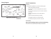
Wiring Diagram POWER TRANSMISSION Belt Drive If using a belt drive application, consider the following notes: • V-belts are preferable to flat belts • The engine drive shaft must be parallel to the machine drive shaft • The engine drive pulley must be in line with the machine drive pulley • Install the engine pulley as close to the engine as possible • Span the drive belt horizontally, if possible.
Operation any indications of fuel leakage. Do not operate engine until all leaks are repaired. ! WARNING EXHAUST GAS IS DEADLY! Exhaust gases contain carbon monoxide, an odorless and colorless gas. Carbon monoxide is poisonous and can cause unconsciousness and death.
3. After the engine starts, slowly push the choke to the fullopen position. Pull it back, if necessary, to keep the engine running smoothly until the engine is at operating temperature In colder weather, the engine will take longer to begin running smoothly with the choke open. Do not operate the equipment until the choke is fully open. OPERATING IN DUSTY CONDITIONS 1. Keep the engine cooling fins and flywheel air inlet screen clean. 2. Perform air cleaner maintenance more often than normal-as required.
! WARNING EXHAUST GAS IS DEADLY! Never operate engine-powered equipment indoors without a proper exhaust system, ample fresh air ventilation and an operable carbon monoxide detector. 2. Use fresh gasoline and fill the fuel tank after each day’s use to reduce problems with moisture condensation if this is a gasoline engine. 6 Perform air cleaner maintenance as instructed in Periodic Maintenance. 7 Plug the exhaust outlet to prevent moisture, dirt, bugs, ect. from entering.
Periodic Maintenance Periodic Maintenance MAINTENANCE, REPLACEMENT, OR REPAIR OF THE EMISSION CONTROL DEVICES AND SYSTEMS MAY BE PERFORMED BY NON-ROAD ENGINE REPAIR ESTABLISHMENTS OR INDIVIDUALS. Periodic maintenance is essential for top engine performance. See the Table below as a guide for normal periodic maintenance. Under hot or dusty operating conditions some maintenance operations should be performed more frequently, as indicated by footnotes in the table.
! WARNING Crankcase pressure can blow hot engine oil out the fill tube causing severe burns. Always stop the engine before removing the oil fill cap. If the engine is equipped with the long oil fill tube, turn the oil fill cap counterclockwise and lift it up. Wipe the dip stick clean, push it back into the oil fill tube until the cap seats. Withdraw it again to check the oil level. CHANGING OIL AND FILTER Change the oil and filter after the first 20 hours of operation.
10 DO NOT FILL TO A LEVEL ABOVE THE FULL MARK ON THE DIPSTICK. Drain the excess oil if too much has been added. Foam Filter Remove and wash the urethane foam in water and detergent. Squeeze the foam wrapper dry like a sponge. Rinse with clean water and allow it to dry. Coat the wrapper evenly with 14 mL (one tbsp.) of SAE 30 engine oil. Knead the oil into the wrapper and squeeze out the excess oil.
SPARK PLUG MAINTENANCE AND REPLACEMENT To adjust the speed control solenoid: Refer to the Specifications for spark plug type and gap specifications. Check and clean spark plugs every 200 hours. Replace plugs every 500 hours. 1 Run the engine with no load until the engine control times out (about 15 seconds) and energizes the solenoid. To prevent cross threading the spark plug, always thread it in by hand until it seats. If the spark plug is being reused, turn it with a wrench and additional 1/4 turn.
Speed Control Adjustments Engine speed adjustment must be attempted only by a qualified mechanic and the adjustments must be made using an accurate tachometer. It is recommended that low-idle speed be adjusted between 2150 to 2250 RPM and high idle speed 3700 to 3800 RPM. Check in your welder manufacture’s manual for exact speed settings. Engine Starting Engine cranks but fails to start Fuel Supply. Check fuel supply and shut-off valve. Check fuel filter and clean if dirty.
Engine Overheats Air flow is obstructed at inlet or cylinder baffle. Clean out debris in baffle. Improper engine oil. Replace oil. Lean air/fuel mixture. Check for plugged passages in carburetor. Excessive back pressure on exhaust. Check muffler and spark arrester. Engine is overloaded. Change to rated load. Engine Idles Rough Low idle speed. Adjust idle on carburetor. Air is mixing at air intake connection. Check, tighten or replace gasket.1 There is blow-by on the head gasket. Replace the gasket.
39 40
Emissions Control System Warranty Statement CALIFORNIA EMISSIONS CONTROL WARRANTY STATEMENT YOUR WARRANTY RIGHTS AND OBLIGATIONS The California Air Resources Board and Fuji Heavy Industries Ltd. (herein “FUJI”) are pleased to explain the emissions control system warranty on your small off-road engine (SORE). InCalifornia, new SOREs must be designed, built and equipped to meet the State’s stringent anti-smog standards.
the part will be repaired or replaced by FUJI according to subsection (4) below. Any such part repaired or replaced under warranty will be warranted for the remainder of the period prior to the first scheduled replacement point for the part. or replacement of the part. That notwithstanding, any adjustment of a component that has a factory installed, and properly operating, adjustment limiting device is till eligible for warranty coverage. The following emissions warranty parts list are covered.
High Altitude Engine Operation How to remove the spark arrestor • Please have an authorized Robin America service dealer modify this engine if it is to be run continuously above 5,000 feet (1,500 meters). Failure to do so, may result in poor engine performance, spark plug fouling, hard starting, and increased emissions. 1. Remove the flange bolts from the muffler cover and remove the muffler cover. 2. Remove the special screw from the spark arrestor and remove the spark arrestor from the muffler.
How to Select a Robin Service Dealer Robin Distribution Method Robin engines and equipment are distributed in North America through a network of independent wholesale distributors. Each authorized Robin wholesale distributor is responsible for stocking Robin products and service parts at each of their distribution warehouses. These distributors supply a network of Robin service dealers with parts, engines, and/or equipment within the distributors assigned marketing area.