2004 IMPREZA SERVICE MANUAL QUICK REFERENCE INDEX ENGINE SECTION 2 This service manual has been prepared to provide SUBARU service personnel with the necessary information and data for the correct maintenance and repair of SUBARU vehicles. This manual includes the procedures for maintenance, disassembling, reassembling, inspection and adjustment of components and diagnostics for guidance of experienced mechanics.
MECHANICAL ME(H4DOTC) 1. 2. 3. 4. 5. 6. 7. 8. 9. 10. 11. 12. 13. 14. 15. 16. 17. 18. 19. 20. 21. 22. 23. 24. 25. 26. Page General Description ....................................................................................2 Compression .............................................................................................34 Idle Speed .................................................................................................35 Ignition Timing................................................
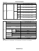
General Description MECHANICAL 1. General Description A: SPECIFICATIONS 1. DOHC TURBO MODEL (EXCEPT FOR STi AND AUSTRALIA MODEL) Type Valve arrangement Bore × Stroke mm (in) Piston displacement 3 Intake valve timing Exhaust valve timing Valve clearance 8.0 kPa (kgf/cm2, psi) Opening Closing Opening Closing Intake Exhaust Belt tension adjuster I.D.: Inner Diameter 700±100 (No load) 800±150 (A/C switch ON) 1→3→2→4 12°±10°/700 BTDC/rpm O.D.
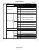
General Description MECHANICAL Refacing angle Valve seat Intake Contacting width Exhaust Valve guide Inner diameter Protrusion above head Intake Head edge thickness Exhaust Valve STD Limit STD Limit Stem diameter Stem oil clearance STD Limit Overall length STD Limit STD Limit Intake Exhaust Intake Exhaust — Intake Exhaust Free length Squareness Valve spring Set Tension/spring height Lift Cylinder block Piston Piston pin Surface warpage limit (mating with cylinder head) Surface grinding limit
General Description MECHANICAL Top ring Piston ring gap Oil ring Piston ring Clearance between piston ring and piston ring groove Connecting rod Second ring Top ring Second ring Bend or twist per 100 mm (3.94 in) in length Side clearance Oil clearance Connecting rod bearing Connecting rod bushing Thickness at center portion Clearance between piston pin and bushing STD Limit STD Limit STD Limit STD Limit STD Limit 0.20 — 0.25 mm (0.0079 — 0.0098 in) 1.0 mm (0.039 in) 0.40 — 0.50 mm (0.016 — 0.
General Description MECHANICAL Bend limit Crank pin and crank journal Crank pin outer diameter Crankshaft Crank journal outer diameter Thrust clearance Oil clearance Out-of-roundness Grinding limit STD 0.03 mm (0.0012 in) US 0.05 mm (0.0020 in) US 0.25 mm (0.0098 in) US STD 0.03 mm (0.0012 in) US 0.05 mm #1, #3, #5 (0.0020 in) US 0.25 mm (0.0098 in) US STD 0.03 mm (0.0012 in) US 0.05 mm #2, #4 (0.0020 in) US 0.25 mm (0.
General Description MECHANICAL #1, #3 Crankshaft bearing Crankshaft bearing thickness #2, #4, #5 STD 0.03 mm (0.0012 in) US 0.05 mm (0.0020 in) US 0.25 mm (0.0098 in) US STD 0.03 mm (0.0012 in) US 0.05 mm (0.0020 in) US 0.25 mm (0.0098 in) US 1.998 — 2.011 mm (0.0787 — 0.0792 in) 2.017 — 2.020 mm (0.0794 — 0.0795 in) 2.027 — 2.030 mm (0.0798 — 0.0799 in) 2.127 — 2.130 mm (0.0837 — 0.0839 in) 2.000 — 2.013 mm (0.0787 — 0.0793 in) 2.019 — 2.022 mm (0.0795 — 0.0796 in) 2.029 — 2.032 mm (0.0799 — 0.
General Description MECHANICAL Belt tension adjuster Protrusion of adjuster rod 5.2 — 6.2 mm (0.205 — 0.244 in) Spacer O.D. Tensioner bush I.D. Belt tensioner Clearance between spacer and bush Side clearance of spacer STD Limit STD Limit Bend limit Thrust clearance Intake Cam lobe height Camshaft Exhaust Journal O.D.
General Description MECHANICAL Cylinder block Piston Piston pin Surface warpage limit (mating with cylinder head) Surface grinding limit A Cylinder bore STD B STD Taper Limit STD Out-of-roundness Limit STD Piston clearance Limit Enlarging (boring) limit A STD B 0.25 mm (0.0098 in) Outer diameter OS 0.50 mm (0.
General Description MECHANICAL Bend limit Crank pin and crank journal Crank pin outer diameter Crankshaft Crank journal outer diameter Thrust clearance Oil clearance Out-of-roundness Grinding limit STD 0.03 mm (0.0012 in) US 0.05 mm (0.0020 in) US 0.25 mm (0.0098 in) US STD 0.03 mm (0.0012 in) US 0.05 mm #1, #3, #5 (0.0020 in) US 0.25 mm (0.0098 in) US STD 0.03 mm (0.0012 in) US 0.05 mm #2, #4 (0.0020 in) US 0.25 mm (0.
General Description MECHANICAL STD 0.03 mm (0.0012 in) US 0.05 mm (0.0020 in) US 0.25 mm (0.0098 in) US STD 0.03 mm (0.0012 in) US 0.05 mm (0.0020 in) US 0.25 mm (0.0098 in) US #1, #3 Crankshaft bearing Crankshaft bearing thickness #2, #4, #5 1.998 — 2.011 mm (0.0787 — 0.0792 in) 2.017 — 2.020 mm (0.0794 — 0.0795 in) 2.027 — 2.030 mm (0.0798 — 0.0799 in) 2.127 — 2.130 mm (0.0837 — 0.0839 in) 2.000 — 2.013 mm (0.0787 — 0.0793 in) 2.019 — 2.022 mm (0.0795 — 0.0796 in) 2.029 — 2.032 mm (0.0799 — 0.
General Description MECHANICAL Belt tension adjuster Protrusion of adjuster rod 5.2 — 6.2 mm (0.205 — 0.244 in) Spacer O.D. Tensioner bush I.D. Belt tensioner Clearance between spacer and bush Side clearance of spacer STD Limit STD Limit Bend limit Thrust clearance Intake Cam lobe height Camshaft Exhaust Journal O.D.
General Description MECHANICAL Cylinder block Piston Piston pin Surface warpage limit (mating with cylinder head) Surface grinding limit A Cylinder bore STD B STD Taper Limit STD Out-of-roundness Limit STD Piston clearance Limit Enlarging (boring) limit A STD B 0.25 mm (0.0098 in) Outer diameter OS 0.50 mm (0.
General Description MECHANICAL Bend limit Crank pin and crank journal Crank pin outer diameter Crankshaft Crank journal outer diameter Thrust clearance Oil clearance Out-of-roundness Grinding limit STD 0.03 mm (0.0012 in) US 0.05 mm (0.0020 in) US 0.25 mm (0.0098 in) US STD 0.03 mm (0.0012 in) US 0.05 mm #1, #3, #5 (0.0020 in) US 0.25 mm (0.0098 in) US STD 0.03 mm (0.0012 in) US 0.05 mm #2, #4 (0.0020 in) US 0.25 mm (0.
General Description MECHANICAL #1, #3 Crankshaft bearing Crankshaft bearing thickness #2, #4, #5 STD 0.03 mm (0.0012 in) US 0.05 mm (0.0020 in) US 0.25 mm (0.0098 in) US STD 0.03 mm (0.0012 in) US 0.05 mm (0.0020 in) US 0.25 mm (0.0098 in) US 1.998 — 2.011 mm (0.0787 — 0.0792 in) 2.017 — 2.020 mm (0.0794 — 0.0795 in) 2.027 — 2.030 mm (0.0798 — 0.0799 in) 2.127 — 2.130 mm (0.0837 — 0.0839 in) 2.000 — 2.013 mm (0.0787 — 0.0793 in) 2.019 — 2.022 mm (0.0795 — 0.0796 in) 2.029 — 2.032 mm (0.0799 — 0.
General Description MECHANICAL B: COMPONENT 1. TIMING BELT • EXCEPT FOR STi AND AUSTRALIA MODEL (2) (1) (2) T7 T2 (3) T1 (2) (4) T2 (5) T1 T3 (6) (12) (9) (7) (8) T1 (14) T5 T4 T4 T1 T4 (2) (10) (14) T2 (11) T4 (17) (13) T5 T1 (15) (16) T6 (18) T1 ME-00601 (1) (2) (3) (4) (5) (6) Timing belt cover No. 2 (RH) Timing belt guide (MT model) Crankshaft sprocket Timing belt cover No.
General Description MECHANICAL • STi AND AUSTRALIA MODEL (2) (1) (2) T2 T2 (3) T1 (2) (4) T2 (5) T1 T3 (9) (12) (6) T5 (7) (8) T4 T3 (14) T1 T5 T1 T5 T4 (2) (10) (14) T2 (11) T4 (17) (13) T5 T1 (15) (16) T6 (18) T1 ME-00704 (1) (2) (3) (4) (5) (6) Timing belt cover No. 2 (RH) Timing belt guide Crankshaft sprocket Timing belt cover No.
General Description MECHANICAL 2.
General Description MECHANICAL (1) (2) (3) (4) (5) (6) (7) (8) (9) (10) Rocker cover (RH) Rocker cover gasket (RH) Oil separator cover Gasket Intake camshaft cap (Front RH) Intake camshaft cap (Center RH) Intake camshaft cap (Rear RH) Intake camshaft cap (RH) Exhaust camshaft cap (Front RH) Exhaust camshaft cap (Center RH) (15) (16) (17) (18) (19) (20) (21) (22) (23) (24) Cylinder head (RH) Cylinder head gasket Cylinder head (LH) Intake camshaft (LH) Exhaust camshaft (LH) Intake camshaft cap (Front LH) I
General Description MECHANICAL • STi AND AUSTRALIA MODEL T2 (2) T5 (1) (4) (5) T1 T5 T3 (10) (8) (3) (12) (13) T3 (7) (6) (9) (11) (13) (28) (14) (24) (25) (26) (10) (18) (17) T4 T5 (11) (27) (22) (21) (28) (20) T2 (15) (16) T3 T3 (19) T5 T2 (23) ME-00705 ME(H4DOTC)-19
General Description MECHANICAL (1) (2) (3) Rocker cover (RH) Rocker cover gasket (RH) Oil flow control solenoid valve assembly (RH) (4) (5) (6) (7) Intake camshaft cap (RH) Intake camshaft (RH) Exhaust camshaft cap (Front RH) Exhaust camshaft cap (Center RH) Exhaust camshaft cap (Rear RH) Exhaust camshaft (RH) Cylinder head bolt Oil seal Cylinder head (RH) (8) (9) (10) (11) (12) (13) (14) (15) (16) (17) Cylinder head gasket Cylinder head (LH) Intake camshaft (LH) Exhaust camshaft (LH) Oil flow control
General Description MECHANICAL 3.
General Description MECHANICAL 4.
General Description MECHANICAL 5.
General Description MECHANICAL 6. ENGINE MOUNTING T2 (3) T2 (3) T1 (2) (2) (1) T1 T3 T3 ME-00706 (1) (2) Heat shield cover Front cushion rubber (3) Front engine mounting bracket ME(H4DOTC)-24 Tightening torque: N·m (kgf-m, ft-lb) T1: 35 (3.6, 25.8) T2: 42 (4.3, 30.9) T3: 85 (8.7, 62.
General Description MECHANICAL C: CAUTION • Wear working clothing, including a cap, protective goggles, and protective shoes during operation. • Remove contamination including dirt and corrosion before removal, installation or disassembly. • Keep the disassembled parts in order and protect them from dust or dirt. • Before removal, installation or disassembly, be sure to clarify the failure. Avoid unnecessary removal, installation, disassembly, and replacement.
General Description MECHANICAL D: PREPARATION TOOL 1. SPECIAL TOOLS ILLUSTRATION TOOL NUMBER 498267600 DESCRIPTION CYLINDER HEAD TABLE REMARKS • Used for replacing valve guides. • Used for removing and installing valve springs. 498457000 ENGINE STAND ADAPTER RH Used with ENGINE STAND (499817000). 498457100 ENGINE STAND ADAPTER LH Used with ENGINE STAND (499817000). 498497100 CRANKSHAFT STOPPER Used for stopping rotation of flywheel when loosening and tightening crankshaft pulley bolt, etc.
General Description MECHANICAL ILLUSTRATION TOOL NUMBER 398744300 DESCRIPTION PISTON GUIDE REMARKS Used for installing piston in cylinder for 2.0 L engine. 498857100 VALVE OIL SEAL GUIDE Used for press-fitting of intake and exhaust valve guide oil seals. 499017100 PISTON PIN GUIDE Used for installing piston pin, piston and connecting rod. 499037100 CONNECTING ROD BUSHING REMOVER & INSTALLER Used for removing and installing connecting rod bushing.
General Description MECHANICAL ILLUSTRATION TOOL NUMBER 499097600 DESCRIPTION PISTON PIN REMOVER ASSY REMARKS Used for removing piston pin. (Except for Australia model) 499097700 PISTON PIN REMOVER ASSY Used for removing piston pin. (Australia model except for STi model) 499207400 CAMSHAFT SPROCKET WRENCH Used for removing and installing exhaust camshaft sprocket and intake camshaft sprocket (RH).
General Description MECHANICAL ILLUSTRATION TOOL NUMBER 499977500 DESCRIPTION CAMSHAFT SPROCKET WRENCH REMARKS Used for removing and installing intake camshaft sprocket. (STi and Australia model) 499587200 CRANKSHAFT OIL SEAL INSTALLER • Used for installing crankshaft oil seal. • Used with CRANKSHAFT OIL SEAL GUIDE (499597100). 499597100 CRANKSHAFT • Used for installing crankshaft oil seal. OIL SEAL GUIDE • Used with CRANKSHAFT OIL SEAL INSTALLER (499587200).
General Description MECHANICAL ILLUSTRATION TOOL NUMBER 18251AA020 DESCRIPTION VALVE GUIDE ADJUSTER REMARKS Used for installing intake and exhaust valve guides. 499767200 VALVE GUIDE REMOVER Used for removing valve guides. 499767400 VALVE GUIDE REAMER Used for reaming valve guides. 499817000 ENGINE STAND • Stand used for engine disassembly and assembly. • Used with ENGINE STAND ADAPTER RH (498457000) & LH (498457100).
General Description MECHANICAL ILLUSTRATION TOOL NUMBER 499977400 DESCRIPTION CRANKSHAFT PULLEY WRENCH REMARKS Used for stopping rotation of crankshaft pulley when loosening and tightening crankshaft pulley bolts. 499987500 CRANKSHAFT SOCKET Used for rotating crankshaft. 498547000 OIL FILTER WRENCH • Used for removing and installing oil filter. • For oil filter (Outer diameter: 80 mm (3.15 in)) 18332AA000 OIL FILTER WRENCH • Used for removing and installing oil filter.
General Description MECHANICAL ILLUSTRATION TOOL NUMBER 499587100 DESCRIPTION OIL SEAL INSTALLER REMARKS Used for installing oil pump oil seal. 499587600 OIL SEAL INSTALLER Used for installing camshaft oil seal for DOHC engine. 499597200 OIL SEAL GUIDE Used for installing camshaft oil seal for DOHC engine. Used with OIL SEAL GUIDE (499587600). 498277200 STOPPER SET ST-499587100 ST-499587600 ST-499597200 ST-498277200 ME(H4DOTC)-32 Used for installing automatic transmission assembly to engine.
General Description MECHANICAL ILLUSTRATION TOOL NUMBER 24082AA230 DESCRIPTION CARTRIDGE REMARKS Troubleshooting for electrical systems. 22771AA030 SUBARU SELECT MONITOR KIT Troubleshooting for electrical systems. • English: 22771AA030 (Without printer) • German: 22771AA070 (Without printer) • French: 22771AA080 (Without printer) • Spanish: 22771AA090 (Without printer) ST24082AA230 ST22771AA030 2. GENERAL PURPOSE TOOLS TOOL NAME Compression Gauge REMARKS Used for measuring compression.
Compression MECHANICAL 2. Compression A: INSPECTION CAUTION: After warming-up, engine becomes very hot. Be careful not to burn yourself during measurement. 1) After warming-up the engine, turn the ignition switch to OFF. 2) Make sure that the battery is fully charged. 3) Release the fuel pressure. 4) Remove all the spark plugs. 5) Fully open the throttle valve.
Idle Speed MECHANICAL 3. Idle Speed A: INSPECTION 1. USING SUBARU SELECT MONITOR 1) Before checking the idle speed, check the following: (1) Ensure the air cleaner element is free from clogging, ignition timing is correct, spark plugs are in good condition, and that the hoses are connected properly. (2) Ensure the malfunction indicator light does not illuminate. 2) Warm-up the engine. 3) Stop the engine, and then turn the ignition switch to OFF. 4) Insert the cartridge to SUBARU SELECT MONITOR.
Ignition Timing MECHANICAL 4. Ignition Timing A: INSPECTION 1. USING SUBARU SELECT MONITOR 1) Before checking the ignition timing speed, check the following: (1) Ensure the air cleaner element is free from clogging, spark plugs are in good condition, and that hoses are connected properly. (2) Ensure the malfunction indicator light does not illuminate. 2) Warm-up the engine. 3) Stop the engine, and then turn the ignition switch to OFF. 4) Insert the cartridge to SUBARU SELECT MONITOR.
Intake Manifold Vacuum MECHANICAL 5. Intake Manifold Vacuum A: INSPECTION 1) Warm-up the engine. 2) Disconnect the brake vacuum hose, and then install the vacuum gauge to hose fitting on manifold. 3) Keep the engine at the idle speed, and then read the vacuum gauge indication. By observing the gauge needle movement, the internal condition of engine can be diagnosed as described below. ME-00008 Vacuum pressure (at idling, A/C “OFF”): Less than −60.0 kPa (−450 mmHg, −17.
Engine Oil Pressure MECHANICAL 6. Engine Oil Pressure A: INSPECTION 1) Remove the oil pressure switch from engine cylinder block. 2) Connect the oil pressure gauge hose to cylinder block. 3) Connect the battery ground cable to battery. FU-00009 4) Start the engine, and then measure the oil pressure. ME-00009 Oil pressure: 98 kPa (1.0 kg/cm2, 14 psi) or more at 800 rpm 294 kPa (3.
Fuel Pressure MECHANICAL 7. Fuel Pressure A: INSPECTION 6) Measure the fuel pressure while disconnecting the pressure regulator vacuum hose from intake manifold. CAUTION: Before removing the fuel pressure gauge, release the fuel pressure. Fuel pressure: Standard; 284 — 314 kPa (2.9 — 3.2 kgf/cm2, 41 — 46 psi) NOTE: If out of specification, check or replace the pressure regulator and pressure regulator vacuum hose. 1) Release the fuel pressure.
Valve Clearance MECHANICAL 8. Valve Clearance 10) When inspecting the #2 and #4 cylinders: (1) Disconnect the battery cable, and then remove the battery and battery carrier. A: INSPECTION Inspection and adjustment of the valve clearance should be performed while engine is cold. 1) Set the vehicle on a lift. 2) Disconnect the ground cable from battery. ME-00013 (2) Remove the bolt which secures the engine harness bracket onto body. FU-00009 3) Remove the air intake duct.
Valve Clearance MECHANICAL (5) Move the washer tank upward. NOTE: If the measured value is not within specification, take notes of the value in order to adjust the valve clearance later on. (A) ME-00017 (6) Disconnect the ignition coil connector. (7) Remove the ignition coil. (8) Place a suitable container under the vehicle. (9) Disconnect the PCV hose from rocker cover (LH). (10)Remove the bolts, and then remove the rocker cover (LH).
Valve Clearance MECHANICAL (3) Set the arrow mark on camshaft sprocket to position shown in the figure, and then measure the #1 cylinder exhaust valve and #4 cylinder intake valve clearances. 3) Remove the valve lifter. 4) Measure the thickness of valve lifter with a micrometer. ME-00025 ME-00736 15) After inspection, install the related parts in the reverse order of removal. Tightening torque: 33 N·m (3.
Valve Clearance MECHANICAL Part No.
Engine Assembly MECHANICAL 9. Engine Assembly A: REMOVAL 1) Set the vehicle on a lift. 2) Open the front hood fully, and then support with the hood stay. 3) Collect the refrigerant from A/C system. 4) Release the fuel pressure. (1) Disconnect the fuel pump relay connector. 10) Remove the intercooler. 11) Disconnect the following connectors and cable.
Engine Assembly MECHANICAL (2) Disconnect the power steering switch connector. (5) Accelerator cable (MT model) ME-00031 ME-00035 (6) Clutch release spring (MT model) (3) Remove the pipe with bracket from intake manifold. ME-00032 12) Disconnect the following hoses. (1) Brake booster vacuum hose ME-00036 (4) Remove the power steering pump from engine. ME-00033 (2) Heater inlet outlet hose ME-00037 (5) Remove the power steering tank from bracket by pulling it upward.
Engine Assembly MECHANICAL (6) Place the power steering pump on right side wheel apron. (2) Remove the plug using a 10 mm hexagon wrench. ME-00039 14) Lift-up the vehicle. 15) Remove the ATF cooler pipe from frame. (AT model) 16) Remove the center exhaust pipe. 17) Remove the nuts which hold the lower side of transmission to engine. ME-00042 (3) Screw the 6 mm dia. bolt into release fork shaft, and remove it.
Engine Assembly MECHANICAL (4) Remove the other bolts while rotating the engine using socket wrench. 25) Support the engine with a lifting device and wire ropes. ME-00047 ME-00044 26) Support the transmission with a garage jack. 22) Remove the pitching stopper. NOTE: Before moving the engine away from transmission, check to be sure no work has been overlooked. Doing this is very important in order to facilitate re-installation and because transmission lowers under its own weight.
Engine Assembly MECHANICAL (3) Remove the bolts which hold the right upper side of transmission to engine. (3) Install the release fork into release bearing tab. (A) (B) ME-00050 28) Remove the engine from vehicle. (1) Slightly raise the engine. (2) Raise the transmission with garage jack. (3) Move the engine horizontally until the mainshaft is withdrawn from clutch cover. (4) Slowly move the engine away from engine compartment.
Engine Assembly MECHANICAL CAUTION: Make sure the cutout portion of release fork shaft contacts spring pin. (B) Tightening torque: 50 N·m (5.1 kgf-m, 36.9 ft-lb) (A) (C) ME-00050 ME-00054 (A) Release fork (B) Release shaft (C) Spring pin 5) Remove the lifting device and wire ropes. 6) Remove the garage jack. (6) Tighten the plug. Tightening torque: 44 N·m (4.5 kgf-m, 32.5 ft-lb) ME-00047 7) Install the pitching stopper. Tightening torque: T1: 50 N·m (5.1 kgf-m, 37 ft-lb) T2: 58 N·m (5.
Engine Assembly MECHANICAL (2) Tighten other bolts while rotating the engine by using ST. CAUTION: Be careful not to drop bolts into the torque converter clutch housing. ST 499977300 CRANKSHAFT PULLEY WRENCH (2) Install the power steering pump. Tightening torque: 20.1 N·m (2.05 kgf-m, 14.8 ft-lb) Tightening torque: 25 N·m (2.5 kgf-m, 18.1 ft-lb) ME-00037 (3) Install the power steering pipe bracket on intake manifold RH. ME-00044 (3) Clog the service hole with plug.
Engine Assembly MECHANICAL (2) Install the air cleaner element and air cleaner upper cover. (3) Install the engine harness connector bracket. (4) Install the filler hose to air cleaner case. 24) Install the A/C pressure hoses. Tightening torque: 50 N·m (5.1 kgf-m, 36.9 ft-lb) NOTE: Use new O-rings. Tightening torque: 25 N·m (2.5 kgf-m, 18.1 ft-lb) ME-00040 15) Tighten the nuts which install the front cushion rubber onto crossmember. Tightening torque: 85 N·m (8.7 kgf-m, 62.
Engine Mounting MECHANICAL 10.Engine Mounting A: REMOVAL 1) Remove the engine assembly. 2) Remove the engine mounting from engine assembly. B: INSTALLATION Install in the reverse order of removal. Tightening torque: Engine mounting; 35 N·m (3.6 kgf-m, 25.8 ft-lb) C: INSPECTION Make sure there are no cracks or other damage.
Preparation for Overhaul MECHANICAL 11.Preparation for Overhaul A: PROCEDURE 1) After removing the engine from body, secure it in the ST shown below. ST1 498457000 ENGINE STAND ADAPTER RH ST2 498457100 ENGINE STAND ADAPTER LH ST3 499817000 ENGINE STAND ST2 ST1 ST3 ME-00057 2) In this section the procedures described under each index are all connected and stated in order. It will be the complete procedure for overhauling of the engine itself when you go through all steps in the process.
V-belt MECHANICAL 12.V-belt 4) Remove the A/C belt tensioner. A: REMOVAL 1. FRONT SIDE BELT 1) Remove the V-belt cover. ME-00061 B: INSTALLATION NOTE: Wipe off any oil or water on the belt and pulley. ME-00708 2) Loosen the lock bolt (A). 3) Loosen the slider bolt (B). 4) Remove the front side belt (C). 1. FRONT SIDE BELT 1) Install a V-belt (C), and tighten the slider bolt so as to obtain the specified belt tension. 2) Tighten the lock bolt (A).
V-belt MECHANICAL 3) Tighten the lock nut (A). Belt tension (without belt tension gauge) Tightening torque: Lock nut (A): 22.6 N·m (2.3 kgf-m, 16.6 ft-lb) (A) When installing new parts: 7 — 9 mm (0.276 — 0.354 in) At inspection: 9 — 11 mm (0.354 — 0.433 in) (B) When installing new parts: 7.5 — 8.5 mm (0.295 — 0.335 in) At inspection: 9.0 — 10.0 mm (0.354 — 0.394 in) (B) (A) 98 N (10 kgf, 22 lb) ME-00060 P/S GEN (A) (B) A/C C: INSPECTION 1) Replace the belts, if cracks, fraying or wear is found.