CONTENTS Section Title Page 1. SPECIFICATIONS ...................................................................................................... 1 2. PERFORMANCE ...................................................................................................... 2 3. FEATURES ............................................................................................................... 7 4. GENERAL DESCRIPTION OF ENGINE COMPONENTS ........................................ 8 5.
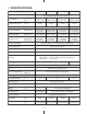
1. SPECIFICATIONS Model EX13D EX17D EX21D EX27D Air-Cooled, 4-Cycle, Slant Single-Cylinder, Horizontal P.T.O. Shaft, OHC Gasoline Engine Type Bore & Stroke mm (in.) Piston Displacement ml (cu.in.) 58 x 48 (2.28 x 1.89) 67 x 48 (2.64 x 1.89) 67 x 60 (2.64 x 2.36) 75 x 60 (2.95 x 2.36) 126 (7.69) 169 (10.31) 211 (12.87) 265 (16.17) Compression Ratio 8.5 8.3 Continuous Output kW(HP)/r.p.m. 1.9(2.6)/3000 2.2(3.0)/3600 2.6(3.5)/3000 2.9(4.0)/3600 3.2(4.4)/3000 3.7(5.0)/3600 4.4(6.
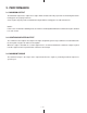
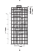
2. PERFORMANCE 2-1 MAXIMUM OUTPUT The Maximum output is the output of an engine with its throttle valve fully opened and considering that all the moving parts are properly broken in. A new engine may not produce full maximum output while its moving parts are still not broken-in. NOTE : Power curves shown in the following charts are made in conformity with SAE internal combustion engine standard test code J1349.
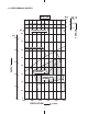
2-4 PERFORMANCE CURVES EX13D 9.0 8.0 MAXIMUM TORQUE kW 4.0 [HP] 5.0 3.5 MAXIMUM HORSEPOWER 4.0 3.0 2.5 OUTPUT 3.0 2.0 CONTINUOUS RATED HP 2.0 1.5 RECOMMENDED HORSEPOWER RANGE 1.0 1.0 0.5 0 0 2000 2400 2800 0.8 0.7 TORQUE 7.0 0.9 3200 REVOLUTION - 3- 3600 r.p.m.
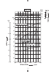
EX17D 11.0 10.0 MAXIMUM TORQUE 9.0 kW [HP] 6.0 4.5 MAXIMUM HORSEPOWER 4.0 5.0 3.5 4.0 3.0 2.5 CONTINUOUS RATED HP OUTPUT 3.0 2.0 RECOMMENDED HORSEPOWER RANGE 2.0 1.5 1.0 1.0 0.5 0 0 2000 2400 2800 REVOLUTION - 4- 3200 3600 r.p.m. 4000 1.2 1.1 1.0 0.9 TORQUE 12.
EX21D 14.0 13.0 MAXIMUM TORQUE 12.0 kW 5.5 [PS] 7.0 5.0 MAXIMUM HORSEPOWER 4.5 6.0 4.0 5.0 3.5 OUTPUT 4.0 3.0 CONTINUOUS RATED HP 2.5 RECOMMENDED HORSEPOWER RANGE 3.0 2.0 2.0 1.5 1.0 1.0 0.5 0 0 2000 2400 2800 3200 REVOLUTION - 5- 3600 r.p.m. 4000 1.5 1.4 1.3 1.2 TORQUE 15.
EX27D 18.0 MAXIMUM TORQUE [HP] 9.0 kW 7.0 1.7 16.0 1.6 15.0 1.5 6.5 6.0 5.5 7.0 6.0 5.0 4.5 CONTINUOUS RATED HP 4.0 5.0 OUTPUT 3.5 4.0 RECOMMENDED HORSEPOWER RANGE 3.0 2.5 3.0 2.0 2.0 1.5 1.0 1.0 0.5 0 0 2000 2400 2800 REVOLUTION - 6- 3200 3600 r.p.m. 1.8 17.0 MAXIMUM HORSEPOWER 8.0 1.9 4000 TORQUE 19.
3. FEATURES 3-1 EXTREMELY SILENT - SOFT TONE QUALITY EX engines are 2dBA quieter and softer in tone than other engines in the same class. This quiet and soft tone is achieved by: - A reduction in mechanical noise realized by employing sophisticated OHC system. - Employment of an optimized capacity Rigid Muffler. 3-2 EXTREMELY EASY START - NO KICK-BACK Reliable Starting and Less Pulling Force are achieved by: - Sophisticated Mechanical Compression Release System as well as newly designed Combustion Chamber.
4. GENERAL DESCRIPTION OF ENGINE COMPONENTS 4-1 CYLINDER AND CRANKCASE The cylinder and crankcase are aluminum die-casting as a single piece. A special cast iron cylinder liner is molded into the aluminum die-casting. The crankcase has a mounting surface on the output shaft side to which the main bearing cover is attached. The cylinder is inclined to the right at an angle of 25 degrees from the horizontal as viewed from the output shaft side. Fig.
4-5 PISTON RINGS The piston rings are made of special cast iron. The profile of the top ring is a barrel face or tapered face, and that of the second ring is a tapered face. There are 2 types of oil ring depending on the engine specification. As those are interchangeable, the cutter ring with coil expander type can be selected as the spare part. 1 1 TOP RING BARREL (EX13/27) TAPER (EX17/21) 2 3 2 3 SECOND RING OIL RING TAPER CUTTER RING WITH COIL EXPANDER THREE-PIECE CONSTRUCTION Fig.
4-9 GOVERNOR SYSTEM GOVERNOR GEAR This engine is equipped with a centrifugal flyweight type governor that makes it possible to operate the engine at a constant speed, even with load variations. (The governor flyweights are mounted on a governor gear.) Fig. 4-9 4-10 COOLING SYSTEM The engine uses a forced air-cooling system in which a cooling fan (which also works as a flywheel) forces cooling air into the cylinder and the cylinder head. Baffles are provided to guide the flow of the cooling air.
4-14 CARBURETOR The engine is equipped with a horizontal draft carburetor. The carburetor setting is calibrated after careful testing for optimum all-round performance (including starting, acceleration, fuel consumption, output power characteristics). Special attention is also paid to the general-purpose use of the engine. (For further information, refer to page 57, section “11. CARBURETOR”.) Fig.
4-18 SECTIONAL VIEW OF THE ENGINE Cross sectional view – across the shaft TANK CAP FUEL TANK GOVERNOR SHAFT BLOWER HOUSING GOVERNOR LEVER GOVERNOR GEAR CRANKSHAFT CONNECTING ROD STARTING PULLEY RECOIL STARTER FLYWHEEL CHARGE COIL (OPTION) OIL SENSOR (OPTION) Fig.
Cross sectional view – along the shaft FUEL STRAINER GOVERNOR LEVER PISTON CHAIN GUIDE MUFFLER MUFFLER COVER EXHAUST VALVE TAIL SCREEN or DEFLECTOR (OPTION) FUEL TANK SPARK ARRESTER (OPTION) GOVERNOR GEAR MAGNETIC SWITCH ROCKER ARM CAMSHAFT INTAKE VALVE TIMING CHAIN PISTON PIN PISTON RING STARTING MOTOR (OPTION) TENSIONER OIL GAUGE FILLER PLUG CONNECTING ROD OIL DRAIN PLUG CRANKCASE CRANKSHAFT OIL SENSOR (OPTION) Fig.
5. DISASSEMBLY AND REASSEMBLY 5-1 PREPARATIONS AND PRECAUTIONS (1) When disassembling the engine, memorize the location of each part so that you can reassemble the engine correctly. If necessary, attach identification tags with the required assembly information to the parts. (2) Store groups of parts in separate boxes. This will make reassembly easier. (3) To prevent parts from being mislaid, keep each group provisionally assembled after removing the parts from the engine.
5-3 DISASSEMBLY PROCEDURE Step 1 Parts to remove Drain the engine oill Remarks and procedures (1) Remove a drain plug (M14×12mm) located on both sides of the case. Take care not to lose the gaskets. (2) To discharge oil quickly, remove the oil guage. Fasteners 14 mm spanner OIL GAUGE GASKET STEP 1 GASKET DRAIN PLUG Fig.
Step Parts to remove Remarks and procedures Air cleaner cover Remove the air cleaner cover. Air cleaner Remove the element, and remove the air cleaner while pulling the breather pipe away from the rocker cover. Fasteners 2 3 STD TYPE 10 mm box spanner M6 nut: 2 pcs. M6 × 20 : 1 pc. DUAL ELEMENT TYPE STEP 3 STEP 3 AIR CLEANER COVER AIR CLEANER COVER URETHAN FOAM PAPER ELEMENT URETHANE FOAM M6 x 20 FLANGE BOLT : 1 pc. AIR CLEANER COVER STEP 2 BREATHER PIPE Fig.
Step Parts to remove Remarks and procedures Fasteners Stop switch Disconnect the wire and remove the stop switch from the blower housing. Recoil starter Remove the recoil starter from the blower housing. 10 mm box spanner M6 × 8mm : 4 pcs. Blower housing Baffle 2 (head) Baffle 3 (1)Remove the blower housing from the crankcase. (2)Remove the baffle 2 (head) and baffle 3. 10 mm box spanner M6 × 12mm : 4 pcs. 10 mm box spanner or spanner M6 × 12mm : 2 pcs. (Baffle 2 (head)) M5 tapping bolt : 2 pcs.
Step Parts to remove Fuel tank Fasteners (1) Drain fuel from the carburetor drain. (2) Remove the fuel tank mounting nuts and bolts from the crankcase. (3) Disconnect the fuel pipe from the carburetor. (See Fig. 5-6) (4) Remove the fuel tank from the crankcase. 7 8 Remarks and procedures Muffler and Muffler cover (1) Remove the muffler cover from the muffler. (2) Remove the muffler from the cylinder head. Take care not to lose the gasket. ※Take care not to cut your hand with the muffler gasket.
Step Parts to remove Governor system (1) Loosen the bolt and remove the governor lever from the governor shaft. There is no need to remove the bolt. (2) Remove the governor spring. (3) Remove the governor rod and the rod spring from the carburetor. Carburetor, Insulator Remove the carburetor from the cylinder head. Remove the insulator. 9 10 11 Fasteners Remarks and procedures 10 mm box spanner or spanner M6 × 30mm : 1 pc.
Step 12 Parts to remove Fasteners Ignition coil Remove the spark plug cap from the spark plug and remove the ignition coil from the crankcase. 10 mm box spanner M6 × 25mm : 2 pcs. Starting pulley Remove the starting pulley from the flywheel. Fit a box wrench or a socket wrench on the flywheel nut and loosen the nut by knocking the wrench sharply with a hammer. (See Fig.
Step 15 Parts to remove Electric starter (option) Control box, Diode rectifier, Magnetic switch Remarks and procedures Fasteners (1) Disconnect the grounding cable from battery. (2) Disconnect the wire leading from the key switch“ST” terminal to the magnetic switch. (3) Disconnect the wire that connects the positive terminal of the battery to the magnetic switch. (4) Remove the electric starter. 12 mm box spanner M8 nuts 10 mm box spanner 12 mm box spanner M6 NUT : 1 pc. (EX17,21) M8 NUT : 1 pc.
Step Parts to remove Remarks and procedures Fasteners Baffle 1 (case) Remove the baffle 1 (case) M6 × 12mm : 1 pc. (Models EX13, 17 and 21) M8 × 12mm : 1 pc. (Model EX27) Charge coil (option) Remove the charge coil. (For EX27, remove the wire clamp together) box spanner M6 × 20mm : 2 pcs. + screwdriver Spark plug Remove the spark plug from the cylinder head. 21 mm plug wrench 16 17 18 BAFFLE 1 (CASE) M6 x 12 FLANGE BOLT : 1 pc. (EX13, 17, 21) M8 x 12 FLANGE BOLT : 1 pc.
Step Parts to remove Remarks and procedures Fasteners Rocker cover (1) Remove the rocker cover from the cylinder head. (2) Remove the gasket (rocker cover). Rocker arm Remove the pin (rocker arm) and the rocker arm from the cylinder head at the compression top dead center. (See Fig. 5-14b) 19 20 ROCKER ARM (EXHAUST VALVE SIDE) PIN (ROCKER ARM) 10 mm box spanner M6 × 12mm : 4 pcs. The position of compression top dead center Punch marks ROCKER ARM (INTAKE VALVE SIDE) Fig. 5-14a Fig.
Step Parts to remove Main bearing cover 21 Remarks and procedures (1) Remove the flange bolts of main bearing cover from the crankcase. Remove the main bearing cover while tapping gently around the cover using a plastic hammer or similar tool. (See Fig. 5-16) Be careful not to damage the oil gauge or oil seal or not to lose the pipe knocks. Fig. 5-16 M8 x 35mm : 6 pcs. (MODELS EX13, 17 AND 21) M8 x 35mm : 7 pcs. (MODEL EX27) STEP 21 PIPE KNOCK MAIN BEARING COVER Fig.
Step Parts to remove Remarks and procedures Tensioner, Camshaft 22 (1) Remove the tensioner. (See Fig. 5-18a) ※Do not lose the pin (tensioner). (2) Remove the retaining bolt of pin (camshaft) from the cylinder head. (See Fig. 5-18b) (3) Remove the pin (camshaft), taking care not to scratch the O-ring. (4) Remove the chain from the camshaft sprocket and then take out the camshaft. (See Fig. 5-19) (5) Remove the chain from the crankshaft. Fasteners M10 box spanner or spanner M6 × 12mm : 1 pc.
Step Parts to remove Fasteners Cylinder head, Chain guide (1) Remove the cylinder head from the 12 mm box spanner crankcase. M8 × 68mm : 4 pcs. (2) Remove the cylinder head gasket from the M8 × 35mm : 1 pc. cylinder head. Take care not to lose the pipe knocks. (3) Remove the chain guide from the top side of the crankcase. (If the chain guide is removed from the inner side of the crankcase, it might be damaged.) Intake and exhaust valves (1) Remove the collet valve from the spring retainer. (See Fig.
Step Parts to remove Connecting rod and piston (1) Scrape off any carbon from the cylinder and the piston head, then remove the connecting rod bolt. (2) Remove the connecting rod cap. (3) Rotate the crankshaft until the piston comes to its top position. Push the connecting rod and remove the piston from the upper part of the cylinder. Piston and piston rings (1) Remove the piston clips (2 pcs.).
Step Parts to remove Remarks and procedures Fasteners Crankshaft (1) Remove the woodruff key (for the flywheel magneto). (2) Remove the crankshaft from the crankcase by tapping its magneto side end with a plastic Plastic hammer hammer, taking care not to damage the oil seal. (See Fig. 5-24) Oil sensor (option) (1) Remove the clamp. (See Fig. 5-25) (2) Remove the oil sensor from the crankcase. 27 28 M6 × 12mm : 1 pc. M6 × 16mm : 2 pcs. CLAMP OIL SENSOR Fig.5-24 Fig.
5-4 REASSEMBLY PROCEDURE 5-4-1 NOTES ON REASSEMBLY (1) Clean the each parts carefully, taking special care with the piston, cylinder, crankshaft, connecting rod and bearings. (2) Scrape off any carbon deposits on the cylinder head and the piston head. Be particularly careful when removing carbon from the piston ring grooves. (3) Inspect the oil seals for any damage to the lip. Replace them if damaged. Apply oil to the lip before reassembly. (4) Replace all the gaskets with new ones.
(3) PISTON AND PISTON RINGS OPEN ENDS OF PISTON RING Install each piston ring in the correct groove of the piston by widening it enough to slide it over the piston. NOTE: Be careful not to twist the rings too much, as they may be damaged. Install the oil ring first, followed by the second ring and then the top ring. When installing the second ring, make sure that the ‘N’ mark is face up. (See Fig. 5-33) Fig.
(4) PISTON AND CONNECTING ROD The piston is attached to the connecting rod by the piston pin. When assembling the piston and connecting rod, make sure to align the mark on the piston head with MAG the ‘MAG’ mark on the connecting rod. NOTE 1: Before assembling the connecting rod, When assembling the piston and connecting rod, make sure to align the mark on the piston head with the ‘MAG’ mark on the connecting rod. apply oil to its small end.
(b) Rotate the crankshaft down to the bottom dead center and lightly tap the piston head until the large end of the connecting rod touches the crank pin. (c) To mount the connecting rod, line up the matching marks and fit the clinch portions firmly together. Tightening torque EX13,17,21 EX27 13.0 - 15.0 N・m (130 - 150 kgf・cm) (9.4 - 10.8 ft・lb.) 17.0 - 20.0 N・m (170 - 200 kgf・cm) (12.3 - 14.5 ft・lb.) ALIGNMENT MARKS ALIGNMENT MARKS (d) Check for free movement of the connecting rod by Fig.
(7) CHAIN GUIDE CHAIN GUIDE Mount the chain guide to the crankcase. Model EX21 mounting position Models EX13, 17 and 27 mounting positions Fig. 5-39b Fig. 5-39a (8) CYLINDER HEAD Inspect and repair any scratches on mounting surface and replace head gasket to new one before installing. Tightening Torque 1st step Cylinder head bolts 1 5 M8 × 68mm flange bolt : 4 pcs. 3 2nd step 1 4 3 2 17.0 - 19.0 N・m (170 - 190 kgf・cm) (12.3 - 13.7 ft・lb.) Remarks 4 2 25.0 - 27.0 N・m (250 - 270 kgf・cm) (18.
(9) SETTING THE TIMING CHAIN (a) Align the timing mark on the crankshaft sprocket with the mark plate of the timing chain. (b) Align the timing mark on the crankshaft sprocket with the mark plate of the opposite end of the timing chain. Model Number of oval steel link EX13 EX17 EX21 EX27 86 88 92 100 CHAIN GUIDE FITTING POSITION Model EX13 MARK PLATE The mark plate does not have a camshaft side or crankshaft sprocket side.
(10) MOUNTING THE CAMSHAFT ON THE CYLINDER HEAD Mount the camshaft on the cylinder head by inserting the pin (camshaft) through the head. Fix the bolt to prevent the pin (camshaft) from coming out. PIN (CAMSHAFT) CHAIN M6 x 12 BOLT : 1 pc. Bolt used to prevent the pin (camshaft) from coming out CAMSHAFT CHAIN CAMSHAFT CHAIN SPRING (TENSIONER) M6 x 12 BOLT : 1 pc. Bolt used to prevent the pin (camshaft) from coming out PIN(CAMSHAFT) TENSIONER PIN(TENSIONER) Fig.
(12) BALANCER SHAFT (OPTION) TIMING MARK (for EX27 only) Mount the balancer shaft on the crankcase, align BALANCER GEAR the timing marks on the balancer gear and the crankshaft gear. NOTE: Incorrect alignment of the timing marks can result in malfunction of the engine, leading to damage due to interference of CRANKSHAFT GEAR the parts. Fig. 5-43 (13) MAIN BEARING COVER Apply oil to the bearing and the oil seal lip when mounting the main bearing cover.
(14) Pass the pin (rocker arm) through the rocker arm ROCKER ARM (EXHAUST VALVE SIDE) PIN (ROCKER ARM) and mount them on the cylinder head. NOTE 1: Conduct this job at the compression top dead center. (The position of two punch marks on cam sprocket is in parallel with the cylinder Punch marks head surface at a time.) NOTE 2: Make sure that the piston is at the The position of compression top dead center compression top dead center by checking ROCKER ARM (INTAKE VALVE SIDE) Fig.
(16) ROCKER COVER SPARK PLUG Replace the gasket with a new one, and mount the rocker cover. M6 ✕ 12mm flange bolt : 4 pcs. Tightening torque 5.0 - 7.0 N・m (50 - 70 kgf・cm) (3.6 - 5.1 ft・lb.) GASKET (ROCKER COVER) (17) SPARK PLUG Remove any carbon deposits from the spark plug and inspect the electrode for damage before mounting. Replace with a new one, if necessary. Tightening torque 0.6 mm - 0.
(19) FLYWHEEL AND STARTING PULLEY FLYWHEEL NOTE: When mounting the flywheel, be sure to wipe off any oil on the tapered portion of the crankshaft and flywheel. Mount the flywheel on the crankshaft. (Tighten the flywheel together with the starting pulley.) STARTING PULLEY Tightening torque Align the 2 bosses of starting pulley with the depression of flywheel. 59.0 - 64.0 N・m (590 - 640 kgf・cm) (42.7 - 46.3 ft・lb.) Fig. 5-50 M14 nut : 1 pc. (EX13, 17, 21) M18 nut : 1 pc. (EX27) Fig.
(21) SPEED CONTROL LEVER, BRACKET AND BAFFLE Mount the speed control lever and bracket, baffle 2 (head) and baffle 3 on the crankcase. NOTE : The baffle 3 is used for Model EX21 only. (22) CARBURETOR (a) Replace the gasket of insulator with a new one and mount the insulator on the cylinder head intake side. (b) Mount the carburetor. M6 x 12 BOLT : 2 pcs. SPEED CONTROL LEVER and BRACKET CARBURATOR INSULATOR GASKET GASKET BAFFLE 2 (HEAD) M6 x 12 BOLT : 1 pce.
(23) GOVERNOR LEVER (a) Pass the governor rod through the rod spring, then connect to the throttle lever of the carburetor. (b) Attach the governor rod and rod spring to the governor lever, then mount the governor lever on the governor shaft. Do not adjust the bolt on the governor lever yet. (c) Connect the governor lever and the speed control lever with the governor spring. NOTE : See page 42 for details on the adjustment method after mounting air cleaner base.
(24) AIR CLEANER BASE M6 x 20 FLANGE BOLT : 1 pc. Insert the breather pipe into the rocker cover AIR CLEANER BASE and then mount the air cleaner base. M6 flange nut : 2 pcs. M6 x 20 mm flange bolt : 1 pc. Tightening torque 6.0 - 8.0 N・m (60 - 80 kgf・cm) (4.3 - 5.8 ft・lb.) BREATHER PIPE M6 FLANGE NUT : 2 pcs. Fig. 5-57 ■ Governor system adjustment method The governor unit is a centrifugal flyweight type and is installed on the governor gear.
(25) MUFFLER (1) Mount the muffler and the gasket on the cylinder head. M6 x 10 TAPPING BOLT : 2 pcs. GASKET (Attention to the wrong side and right side) MUFFLER SIDE (RIGHT SIDE) M6 x 8 FRANGE BOLT : 1 pc. M8 NUT : 2 pcs. CYLINDER SIDE (WRONG SIDE) MUFFLER Take utmost care not to cut your hand with the muffler gasket M8 ✕12 mm bolt : 1 pc. M8 x 12 BOLT : 1 pc. M8 nut : 2 pcs. Tightening torque GASKET (Attention to the wrong side and right side) 18.0 - 22.0 N・m (180 - 220 kgf・cm) (13.0 - 15.
(3) Mount the fuel tank on the crankcase. FUEL PIPE M6 nut : 2 pcs. M6 ✕ 25 mm bolt : 1 pc. (Models EX13, 17 and 21) M8 ✕ 25 mm bolt : 2 pcs. (Model EX27) BOSS Fig. 5-59c (27) BLOWER HOUSING AND RECOIL STARTER (1) Mount the ignition coil cord on the crankcase by aligning it with the baffle 1 (case). (2) Mount the blower housing on the crankcase. M6 × 12 mm bolt : 4 pcs. (3) Mount the recoil starter on the blower housing. M6 × 8 mm bolt : 4 pcs. M6 x 8 BOLT : 4 pcs. M6 x 12 BOLT : 4 pcs.
(28) STOP SWITCH STOP SWITCH (1) Mount the stop switch on the blower housing. (2) Refer to the wiring diagram (See page 51 and 52) for wiring details. Fig. 5-61 (29) AIR CLEANER Mount the air cleaner element and cleaner cover. Type STD Fig.
(30) EXTERNAL INSPECTION Reassembly is completed. Check that the wiring is correct and that there are no loose nuts and bolts or any other faults visible on the outside of the engine. (31) FILLING WITH ENGINE OIL Use the automobile engine oil of API service class SE or higher grade. The amount of oil depends on the engine model. Refer to the table below. Model EX13 Model EX17 Engine oil volume Model EX21 0.6 L Model EX27 1.
6. ENGINE OIL Using engine oil of the correct grade and viscosity greatly lengthens engine life and improves performance. Too much or too little oil can also result in serious problems, including engine seizure.
7. MAGNETO 7-1 MAGNETO The Robin Engine uses a T.I.C. type breakerless magneto ignition system. (1) T.I.C. (TRANSISTOR IGNITER CIRCUIT) has the ignition coil outside the flywheel, which is the standard specification. A charge coil system is available as an option. (The flywheel is a specialized piece of equipment.) As for the lighting coil, the ignition coil is outside the flywheel and a lighting coil is inside.
7-3 IGNITION SYSTEM (EX13 ,17, 21) 7-3-1 TYPE OF IGNITION SYSTEM Secondary Coil Primary Coil I2 I4 Spark Plug I5 Ignition Coil Automatic Advancing Control Circuit Power Transistor LowSpeed I3 Ignition Timing Control Circuit I1 Signal Transistor B Signal Transistor A Resister EX13, 17 and EX21 have the T.I.C. (Transister, Igniter, Circuit) pointless ignition system. As optional parts, these ignition system may be implemented with lamp coil, charge coil and excitor coil. I6 Fig.
7-4 IGNITION SYSTEM (EX27) IGNITION COIL INTERNAL CIRCUIT Low Speed Ignition Timing Control Circuit Advancing Control Circuit I4 I5 4 7 1 Spark Plug I3 2 Secondary Coil Control thyristor 5 3 I2 Primary Coil I1 Power Transistor Base Resister Revolution Sensing Resister 7-4-1 6 Fig.7-2a 7-4-2 IGNITION TIMING CHARACTERISTIC LINEAR ADVANCING 35 IGNITION TIMING B.T.D.C. ( ) 30 25 20 15 10 5 0 0 500 1000 1500 2000 2500 3000 3500 4000 ENGINE REVOLUTION (R.P.M.) Fig.
8. WIRING DIAGRAM 8-1 MODEL WITHOUT ELECTRIC STARTER (Models EX13, 17, 21 and 27) Spark plug Stop switch Black Ignition coil (with built-in transistor) Flywheel Fig. 8-1 8-2 MODEL WITH ELECTRIC STARTER (Models EX17 and 21) Spark plug Black Magneto Ignition coil Key switch +M -M Charge coil Diode rectifier LA306 ST B Red LA106 LA406 Key switch 066-00003-30 -M OFF ON START +M B S Magnetic switch Electric starter Fig.
8-3 MODEL WITH ELECTRIC STARTER (Model EX27) Spark plug Black Magneto Ignition coil Key switch +M -M Charge coil Diode rectifier ST B LA108 LA408 Red Battery (12V24AH) Key switch 066-00003-30 -M +M B S OFF ON START Electric starter Fig. 8-3 8-4 MODEL WITH OIL SENSOR To LED Lamp Yellow Yellow / Red Oil sensor Orange Black Black / White control unit Body earth LA106 Black Orange Oil sensor To stop switch Spark plug ※ Oil sensor as option Fig.
9. ELECTRIC STARTER EX 17, 21 9-1 SPECIFICATIONS 129.5 Models EX17, 21 Pinion gear Model EX27 Voltage (V) 12 Power (kW) 0.6 0.6 Weight (kg) 1.6 3.4 EX 27 PINION GEAR 157.8 Fig. 9-1 9-2 OPERATING PRINCIPLES The battery is connected to the 6 or 8 mm diameter terminal of the magnetic switch. The figure below shows the state when the starter is ON. M M S S M M ELECTRIC STARTER MAGNETIC SWITCH BATTERY M KEY SWITCH Fig.
9-3 COMPONENT PARTS (Models EX17 and EX21) PINION AY FRONT COVER MAGNETIC SWITCH PINION STOPPER SET BATTERY CABLE THROUGH BOLT (2 pcs.) O - RING WASHER YOKE AY O - RING ARMATURE AY BRUSH SPRING (BRUSH) REAR COVER BRUSH HOLDER (Model EX27) MAGNETIC SWITCH PINION AY ARMATURE AY YOKE AY SPRING (BRUSH) BRUSH FRONT COVER CASE METAL BRUSH HOLDER REAR COVER FRONT METAL THROUGH BOLT (2 pcs.) PINION STOPPER SET Fig.
10. OIL SENSOR 10-1 SPECIFICATIONS Type Float type (with lead switch incorporated) Resistance (at FULL oil level) 100 M ohms or over Operating Temperature -30 to +180 degree Celsius OIL SENSOR Fig.10-1 10-2 CONSTRUCTION AND OPERATION The oil sensor is composed of the float, permanent magnet incorporated into the float and the oil sensor. In accordance with the oil level, the float moves up and down. When the oil level is upper level, the float moves up. FLOAT PERMANENT MAGNET LEAD SWITCH Fig.
11. AUTOMATIC DECOMPRESSION SYSTEM 11-1 FUNCTIONS AND CONSTRUCTION EX series engines employ an automatic decompression system as a standard feature. This enables easy starting of the engine, with lighter recoil pull. The automatic decompression system releases the compression of the engine by lifting up the exhaust valve at cranking speed. The following is the explanation of the function.
12. CARBURETOR 12-1 SPECIFICATIONS EX13 EX17 EX21 EX27 A/C Type STD DUAL STD DUAL STD DUAL STD DUAL Main Jet 70.0 68.8 81.3 80.3 86.3 83.8 98.0 96.0 Pilot Jet 40.0 40.0 40.0 40.0 41.3 ← 40.0 ← Pilot Screw Turning 1-3/4 ← 1-1/4 ← 1 ← 1-1/2 ← 12-2 FUNCTIONS AND CONSTRUCTION 12-2-1 FLOAT SYSTEM The float chamber is located below the carburetor body.
FUEL SYSTEM OUTLINE FUEL NEEDLE VALVE FLOAT FLOAT CHAMBER Fig. 12-1 PILOT OUTLET PILOT JET BYPASS PILOT AIR JET MAIN NOZZLE AIR INTAKE PORT CHOKE VALVE FLOAT MAIN AIR JET MAIN JET Fig.
12-3 DISASSEMBLY AND REASSEMBLY Mechanical failures aside, most carburetor malfunctions occur when the fuel/air ratio of the mixture is not correct. This is usually caused by clogged jets, air passages and fuel passages, or by variations in the fuel level. To get the best possible performance from the carburetor, ensure that the each passages are kept clean so that air and fuel can flow freely through them.
The procedures for overhauling the carburetor are described below. (Refer to Fig. 11-3.) 12-3-1 THROTTLE SYSTEM (1) When the throttle stop screw 26 is removed, the spring 25 can be taken out. (2) Remove the phillips screw 22 and the throttle valve 23, then take out the throttle shaft 24 . When removing the throttle valve, take care not to damage the valve edge. 12-3-2 CHOKE SYSTEM (1) Remove the choke valve ⑭. Then pull out the choke shaft ⑬.
13. RECOIL STARTER 13-1 RECOIL STARTER Tools required: Screwdriver, pliers and protective glasses NOTE: Put on the protective glasses prior to start disassembly. 13-1-1 DISASSEMBLY PROCEDURE (1) Release the reel spring power -1 Hold the starter knob and pull out the starter rope. -2 Pull out the rope fully and align the rope knot in the reel with the rope guide. -3 Hold the reel down firmly with both thumbs, taking care not to allow it to spring back. (Fig.
(2) Remove the components. (Fig. 13-2) -1 Grip the case and loosen the set screw. SET SCREW -2 Take out the set screw, the ratchet guide, RATCHET GUIDE the friction spring and the ratchet in that order. FRICTION SPRING (3) Remove the reel. (Fig. 13-2) -1 Hold down the reel gently to keep it from RATCHET escaping from its case and rotate it slowly back and forth by quarter turns until it moves smoothly. REEL -2 Lift the reel up little by little and take it out of the case.
(2) Mount the components -1 Mount the ratchet into the reel. (Fig. 13-5) THE RATCHET SHOULD BE IN THE CLOSED POSITION Fig. 13-5 -2 Mount the ratchet guide assembly, taking care Set screw not to move the ratchet. (Fig.13-6) Ratchet guide Friction spring Ratchet guide sub-assembly Fig. 13-6 (3) Tighten the set screw -1 Hold the ratchet guide gently by your hand to prevent it from rotating, then tighten the set ROPE HOLE IN REEL screw. Tightening torque(M6) 5.5 N・m (55 kgf・cm) (4.0 ft・lb.
(5) Install the rope NOTE: This procedure requires 2 people. -1 Pass the rope end through the rope guide and the Approx. 20mm rope hole of the reel and pull through approximately 20 cm out of the reel. (Fig. 13-7) -2 Tie a knot in the rope end . (Fig. 13-8) -3 Put the rope into the reel, taking care that the rope end does not stick up. (Fig. 13-9) -4 Grasp the rope firmly with one hand at approximately 50 cm from the rope guide and keep the rope tense, taking care that the rope Fig.
13-1-3 CHECKING THE RECOIL STARTER AFTER REASSEMBLY (1) Pull the starter knob about 2-3 times. (a) If the starter knob is too heavy to pull, check that each parts have been assembled as specified. (b) If the ratchet does not work, check for missing parts such as the friction spring. (2) Pull out the starter knob as far as it will go. (a) If the starter rope remains in the rope slot in the reel, the spring may be over-stressed.
14. INSTALLATION Installation has a decisive influence on engine life, ease of maintenance and inspection, frequency of inspection and repair, running costs and other related aspects. Before installing the engine, be sure to plan the installation with care, taking the points below into account. 14-1 INSTALLING When installing the engine, pay special attention to the position of installation, the method for coupling with working equipment, and the foundations and supports for the engine.
14-5 POWER TRANSMISSION TO DRIVE MACHINES 14-5-1 BELT DRIVE Note the following: • Use a V-belt rather than a flat belt. • The drive shaft of the engine must be parallel to the drive shaft of the driven machine. • The drive pulley of the engine must be in line with the driven pulley of the machine. • Install the engine pulley as close to the engine as possible. • If possible, span the belt horizontally. • Disengage the load when starting the engine.
15. TROUBLESHOOTING If the engine shows any sign of malfunction, the cause should be determined immediately and appropriate countermeasures should be taken to prevent the problem from worsening. This section describes certain known problems, their possible causes and appropriate countermeasures. Note, however, that the list of problems presented here is not all.
Problem and possible cause Poor output 1. Insufficient compression 1) Loosen spark plug Retighten; replace gasket 2) Leakage from cylinder head gasket Retighten; replace gasket 3) Piston ring seizure or wear Replace 4) Piston or cylinder wear Repair or replace 5) Incorrect valve and seat contact Repair or replace 6) Valve stem seizure Repair or replace 7) Improper valve clearance Adjust 2.
Problem and possible cause High fuel consumption Excessive engine oil consumption 1. Oil leakage 2. Oil up 1.
ELECTRIC STARTER Engine does not start Does the crank run? NG Does the starter run? Check battery charged state and battery terminal connection or corrosion for any abnormality. NG Charge or replace the battery. Repair connection or corrosion of battery terminals. NG Key switch Connected state Check/repair wiring to the starter magnetic switch. Repair or replace starter magnetic switch. OK Operation sound of magnetic switch of starter OK NG OK Check settling of spring and sliding of pinion.
Problem and check item (1) Starter does not run or only “click” sound is heard. 1. Checking of continuity of wiring Description Check S terminal and B terminal for deformation, looseness, rusting, or dust sticking. Carefully check inserting method of the S terminal. If not abnormal, set the key switch to START position while cranking (no ignition of engine) and check if voltage is applied to the S terminal and B terminal of starter motor. Remedy KEY SWITCH (+) S (-) B 4.
Problem and check item Description Remedy (1) Remove and check the starter. Check or replace the pinion clutch if necessary. (2) Check battery charged state and battery terminal connection or corrosion for any abnormality. If pinion and ring gear do not engage with each other and abnormal noise is heard between end faces of pinion and ring gear, check the starter pinion and ring gear. (1) Remove the starter and check pinion and ring gear end faces. If worn, replace the pinion and ring gear.
16. STANDARD REPAIR TABLES “STD” in the following table is the parts dimension from the brand new engine or the spare parts. Whereas, “Limit” shows the maximum allowance for the parts to be used on the engine. If the measurement exceeds beyond the “Limit”, the part needs to be replaced and/or repaired. 16-1 STANDARD DIMENSIONS AND LIMITS OF USE ITEM Unit: mm (in.) STD Limit EX13 EX17 EX21 EX27 0.05 (0.002) 0.1 (0.004) Intake Exhaust EX13 EX17 EX21 EX27 0.7 - 1.0 (0.0276 - 0.
Unit: mm (in.) ITEM STD CYLINDER * Inner diameter EX13 Standard EX17 EX21 EX27 EX13 First reboring EX17 EX21 EX27 EX13 Second reboring EX17 EX21 EX27 EX13 EX17 EX21 EX27 * Roundness after reboring EX13 EX17 EX21 EX27 * Cylindricity after reboring PISTON * Outer diameter at skirt in thrust direction EX13 Standard EX17 EX21 EX27 EX13 Oversize +0.25 EX17 EX21 EX27 EX13 Oversize +0.50 EX17 EX21 EX27 - 75 - Limit 58.000 - 58.019 (2.2835 - 2.2842) 67.000 - 67.019 (2.6378 - 2.6385) 75.
Unit: mm (in.) ITEM PISTON * Ring groove side clearance STD Top Second EX13 EX17 EX21 EX27 EX13 Oil ring Coil exp EX17 EX21 EX27 EX13 Oil ring (three-piece) EX17 EX21 EX27 * Piston pin hole EX13 EX17 EX21 EX27 * Piston pin outer diameter EX13 EX17 EX21 EX27 * Clearance between piston and cylinder at skirt EX13 Limit 0.035 - 0.080 0.15 (0.0014 - 0.0031) (0.0059) 0.02 - 0.075 (0.0008 - 0.0031) 0.01 - 0.065 0.15 (0.0004 - 0.0026) (0.0059) 0.01 - 0.065 (0.0004 - 0.0026) 0.060 - 0.165 (0.
Unit: mm (in.) ITEM STD CONNECTING ROD * Large end inner diameter EX13 EX17 EX21 EX27 * Clearance between large end and crank pin EX13 EX17 EX21 EX27 * Small end inner diameter EX13 EX17 EX21 EX27 * Clearance between small end and piston pin EX13 EX17 EX21 EX27 Limit 30.000 - 30.016 30.1 (1.1811 - 1.1817) (1.1850) 34.500 - 34.516 34.1 (1.3386 - 1.3392) (1.3425) 0.020 - 0.049 0.2 (0.0008 - 0.0019) (0.0078) 13.010 - 13.021 13.08 (0.5122 - 0.5126) (0.5150) 16.010 - 16.021 16.08 (0.
Unit: mm (in.) ITEM STD Limit CAMSHAFT * Cam peak height (intake and exhaust) Cam peak height EX13 EX17 EX21 EX27 Cam inner diameter D1,D2 EX13 EX17 EX21 EX27 Pin outer diameter D3,D4 EX13 EX17 EX21 EX27 Intake EX13 EX17 EX21 EX27 Exhaust EX13 EX17 EX21 EX27 Intake EX13 EX17 EX21 EX27 Exhaust EX13 EX17 EX21 EX27 Intake EX13 EX17 EX21 EX27 Exhaust EX13 EX17 EX21 EX27 29.028 - 29.128 28.98 (1.1428 - 1.1468) (1.1409) 9.0 - 9.036 9.05 (0.3543 - 0.3557) (0.
Unit: mm (in.) ITEM STD Limit VALVE SPRING FREE LENGTH EX13 EX17 EX21 EX27 27.4 (1.0787) VALVE SEAT ANGLE (INTAKE AND EXHAUST) * Valve cutter angle (a) * Valve contact width (b) Intake Exhaust EX13 EX17 EX21 EX27 a: 90° b: 0.7 - 1.0 2.0 (0.0787) (0.0276 - 0.0394) CHAIN LENGTH EX13 263.1 266.0 (10.3583) (10.4726) 160N (16kgf.) F EX17 269.0 272.1 (10.5906) (10.7126) L EX21 L EX27 Compression pressure Fuel consumption Lubricant 284.9 (11.2165) 307.1 310.6 (12.0906) (12.
16-2 TIGHTENING TORQUE Tightening Torque ITEM N・m kgf・cm ft・lb. 25.0 - 27.0 250 -270 18.1 - 19.5 M8 × 68 flange bolt When replace to new cylinder head and flange bolts 28.0 - 30.0 280 - 300 20.3 - 21.7 M8 × 35 flange bolt 17.0 -19.0 170 - 190 12.3 - 13.7 EX13,17,21 13.0 - 15.0 130 - 150 9.4 - 10.8 EX27 17.0 - 20.0 170 - 200 12.3 - 14.5 Flywheel nut 59.0 - 64.0 590 - 640 42.7 - 46.3 Main bearing cover bolts 22.0 - 24.0 220 - 240 16.2 - 17.7 New 12.0 - 15.0 120 - 150 8.7 - 10.
17. MAINTENANCE AND STORAGE The maintenance jobs described below apply to correct use of the engine under normal conditions. The maintenance intervals mentioned in this section are not a guarantee that no maintenance is required during those intervals. For example, when the engine is used in dusty conditions, the air cleaner should be cleaned every day, rather than every 100 hours. 17-1 DAILY MAINTENANCE (EVERY 8 HOURS OF USE) MAINTENACE ITEMS REASON / REMARKS (1) Clean dust from engine.
17-5 INSPECTION AND MAINTENANCE EVERY 300 HOURS MAINTENACE ITEMS (1) Inspect the intake and exhaust valve clearance. Adjust if necessary. 17-6 REASON / REMARKS (1) Incorrect clearance can cause low power output and engine malfunction. INSPECTION AND MAINTENANCE EVERY 500 TO 600 HOURS (EVERY 6 MONTHS) MAINTENACE ITEMS REASON / REMARKS (1) Remove the cylinder head and remove any carbon. (1) Carbon deposits can cause engine malfunction. (2) Disassemble and clean the carburetor.
1934 2004.