PARTS MANUAL Models EX13, EX17, EX21 ENGINE PUB-EP1676 Rev.
905 Telser Rd. • Lake Zurich, IL 60047 • Phone: 630-350-8200 • Fax: 630-350-8212 © Copyright 2008 Robin America, Inc. e-mail: sales@robinamerica.com • www.robinamerica.
HOW TO USE THIS MANUAL Robin engines are identified by MODEL, SPECIFICATION, and CODE NUMBER. For each model there may be many different versions called specifications. Each specification will be unique in some way. The difference may only be the paint color or it may have a different type of PTO or some other significant difference. In order the identify the correct service part number, it is important to confirm the specification and code numbers for your engine.
MANUAL LAYOUT 1 4 3 2 1 6 7 9 2 3 5 8 4 1. SECTION NAME Parts are broadly classified according to their functions. Refer to the Group Index (table of contents) for respective section name. 2. FIG. No. The FIG. number indexes the reference and part numbers to the illustration. Figure numbers that vary only in the tens place (i.e..: 700 and 710) are in a group of the same section (i.e..:Electrical Device Group). 3. REF. No .
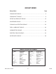
GROUP INDEX Group Name Page CRANKCASE GROUP ............................................................................... 6 CRANKSHAFT GROUP ............................................................................. 8 INTAKE and EXHAUST GROUP .............................................................. 10 GOVERNOR GROUP .............................................................................. 18 COOLING and STARTING GROUP .........................................................
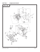
SECTION 1 CRANKCASE GROUP FIG.
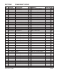
SECTION 1 REF. 10 10 10 20 26 30 40 50 60 70 75 80 90 210 220 230 250 260 270 280 281 300 610 610 610 620 630 631 680 690 700 710 850 960 PART NO.
SECTION 2 CRANKSHAFT GROUP FIG.
SECTION 2 REF. 10 10 10 50 70 310 310 310 320 350 360 360 370 370 371 PART NO.
SECTION 2 CRANKSHAFT GROUP FIG.
SECTION 2 REF. 371 380 PART NO. 277-23531-07 277-23532-07 277-23533-07 215-25004-03 056-51600-10 EX13, EX17, EX21 CRANKSHAFT GROUP DESCRIPTION Piston Ring Set - DE Piston Ring Set - DE Piston Ring Set - DE Clip Clip QTY. REMARKS 1 EX17, 21 - STD 1 EX17, 21 - Oversize 0.25mm 1 EX17, 21 - Oversize 0.50mm 2 EX13 2 EX17, 21 - 11 - FROM-TO FIG.
SECTION 3 INTAKE and EXHAUST GROUP - New Style FIG.
SECTION 3 REF. 10 25 27 34 35 37 38 60 70 80 90 95 150 160 163 166 170 200 202 220 225 230 240 290 310 315 317 320 340 350 360 361 365 385 387 440 445 PART NO.
SECTION 3 INTAKE and EXHAUST GROUP - Old Style FIG.
SECTION 3 REF. 10 25 27 34 35 37 38 60 70 80 90 95 150 160 163 166 170 200 220 225 230 231 240 241 290 310 310 315 317 320 340 350 360 361 365 385 387 440 445 PART NO.
SECTION 3 INTAKE and EXHAUST GROUP FIG.
SECTION 3 REF. 510 -200 -210 -220 -250 -260 -270 -290 520 570 580 PART NO.
SECTION 3 INTAKE and EXHAUST GROUP FIG.
SECTION 3 REF. 510 -200 -200 -200 -210 -220 -250 -260 -270 -272 -310 -315 520 570 580 PART NO.
SECTION 4 GOVERNOR GROUP - New Style FIG.
SECTION 4 REF. 10 20 30 40 50 60 70 80 310 340 350 355 360 365 370 395 396 435 440 450 480 485 486 PART NO.
SECTION 4 GOVERNOR GROUP - Old Style FIG.
SECTION 4 REF. 10 20 30 30 40 50 60 70 80 310 340 350 355 360 365 370 395 396 435 440 450 480 485 * PART NO.
SECTION 5 COOLING and STARTING GROUP FIG.
SECTION 5 REF. 10 10 10 20 40 60 61 62 80 81 82 110 210 220 400 PART NO.
SECTION 5 COOLING and STARTING GROUP FIG.
SECTION 5 REF. 210 -1 -2 -3 -4 -5 -6 -7 -11 -35 -49 PART NO.
SECTION 6 FUEL, LUBRICATION GROUP FIG.
SECTION 6 REF. PART NO.
SECTION 6 FUEL, LUBRICATION GROUP FIG.
SECTION 6 REF. 210 210 210 -1 -2 -3 -4 -5 -8 -9 -11 -11 -12 -13 -14 -15 -16 -17 -18 -19 -20 -22 -22 -22 -24 -28 PART NO.
SECTION 6 FUEL, LUBRICATION GROUP FIG.
SECTION 6 REF. PART NO. -40 106-62556-08 -41 283-62357-08 -44 207-62410-08 248-62410-08 106-62411-08 -45 106-62410-08 -62 236-62680-08 -79 236-62541-08 -102 246-62390-08 -144 277-62553-08 -300 279-62103-10 -302 277-62110-18 -303 277-62100-18 -325 277-62552-08 -327 165-62377-08 EX13, EX17, EX21 FUEL, LUBRICATION GROUP DESCRIPTION Screw Spring Air Jet Air Jet Air Jet Air Jet, pilot Seal Packing Seal Nut Fuel Strainer Ay Packing Cup O ring Screw QTY.
SECTION 7 ELECTRIC DEVICE GROUP FIG.
SECTION 7 REF. 10 10 10 11 12 13 14 20 23 30 35 36 37 38 50 60 70 80 100 110 700 705 740 741 770 775 780 PART NO.
SECTION 7 ELECTRIC DEVICE GROUP FIG.
SECTION 7 REF. 55 120 128 130 131 190 200 210 220 -1 230 240 260 335 384 385 PART NO.
SECTION 9 ACCESSORY GROUP FIG.
SECTION 9 REF. 10 PART NO. 277-90301-H0 EX13, EX17, EX21 ACCESSORY GROUP DESCRIPTION ACCESSORY KIT QTY. REMARKS 1 - 39 - FROM-TO FIG.
Procedure for Converting Active Carbon Canister to a Passive Cap/Canister 1. Remove carbon canister purge hose from the back side of the air cleaner by pulling the hose off using needle nose pliers. 2. Install the plastic cap (P/N 84735K12) onto the nipple that the hose was removed from. Fully seat the plastic cap using your fingers. 3. Remove the top two screws on the recoil to remove the hose clamps. After the clamps have been removed, reinstall the two top screws. 4.
Notes: EX13, EX17, EX21 - 41 - 09-08
PRINTED IN THE USA Robin America, Inc 905 TFMTFS 3PBE t -BLF ;VSJDI *- 60047 1IPOF t 'BY F NBJM TBMFT!TVCBSVQPXFS DPN t XXX TVCBSVQPXFS.