
Instructions / Assembly


3
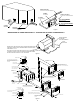
H. Install chocks, one on each side of water heater, as illustrated in Figure 3.
I. Attach door to frame as illustrated.
J. Close the door so that the door latch protrudes through the slot in the door. Turn
latch 90 degrees to fasten door.
K. The module board on all models EXCEPT DEM models, is not secured to the
water heater. It is to be permanently mounted by the installer.
The module board must be mounted to where it is accessible for service yet out
of way of children. It should be located in a place where it cannot be subjected
to moisture, cleaning chemicals, ammable vapors and liquids, etc. The board
and all wiring to the board must be protected in order to prevent damages and
accidental contact with these parts. The module board may be mounted with two
(2) No. 6 x 5/8 screws or other suitable hardware.
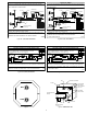
INSTALLATION USING FLUSH MOUNT
FRAME & DOOR (See Figure 4)
A. Position heater into framed opening as illustrated. Slide unit into opening until the
front of the control housing is ush with the exterior coach skin.
B. Secure the control housing to the coach wall (framed opening) at the top and sides
of control housing compartment using screws or other suitable fasteners. Recess
the screws or fasteners back far enough from the front edge of control housing
(approximately 1 1/2”) in order to clear the ange on door frame. The door frame,
when installed, must not overlap onto screw or other fastener head. If due to the
wall thickness, it is not possible to secure the water heater without covering the
fastener head with the door frame, it is important to not over tighten the fastener
and distort the control housing. Over tightening of the fastener may cause water
heater leaks between the control housing and the door frame.
NOTE: Caulk around screw or fastener heads to assure water tight seal.
C. Install chocks, one on each side of water heater, as illustrated in Figure 3.
D. On mesa or yoder type sidewalls, atten the wall area around the opening.
E. Caulk around framed opening (trailer skin) as illustrated.
F. Caulk around door frame using 2 beads of silicone caulking (or suitable caulking) -
one on ange to seal to control housing and one around back side of frame to seal
to coach skin. See detail “A” in illustration.
G. Insert door frame into control housing and secure with the No. 8-15 x 3 1/2” screws
provided.
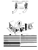
H. To install door, place the two holes in the bottom of the door over the door pins on
the frame. Close the door so that the latch protrudes through the slot in the door.
Turn latch 90 degrees to fasten door.
I. The module board on all models EXCEPT DEM models is not secured to the water
heater. It is to be permanently mounted by the installer.
The module board must be mounted to where it is accessible for service yet out
of way of children. It should be located in a place where it cannot be subjected
to moisture, cleaning chemicals, ammable vapors and liquids, etc. The board
and all wiring to the board must be protected in order to prevent damages and
accidental contact with these parts. The module board may be mounted with two
(2) No. 6 x 5/8 screws or other suitable hardware.
MAKING ELECTRICAL CONNECTIONS
12 VOLTS D.C.
A. Refer to Figure 4 for location of D.C. junction box. For DEM model D.C. junction
box location, please refer to Figure 8.
B. The electrical connections must be made in accordance with local codes and
regulations. In the absence of local codes and regulations, refer to the latest
edition of the National Electrical Code NFPA 70.
In Canada, the electrical installation should conform with CSA standard Z240.6.2-08/
C22.2 No. 148-08 Electrical Requirements for Recreational Vehicles and CSA C22.1
Canadian Electrical Code Part 1 when installing the unit in recreational vehicles and
mobile homes respectively.
C. Make the 12 Volt D.C. electrical connections following the wiring diagrams
illustrated in Figure 5A and 5B
If the power supply is to be from a converter, we recommend that the converter system
be wired in parallel with the battery. This will serve two purposes:
1. Provide a constant voltage supply
2. Filter any A.C. spikes or volt surges
We recommend insulated terminals be used for all electrical connections.
MAKING ELECTRICAL CONNECTIONS
120 VOLTS A.C.
A. Applicable to DE, DEC, DEL, DELC and DEM models.
B. Refer to Figure 4 for location of A.C. junction box. For DEM model A.C. junction
box location, please refer to Figure 8.
C. The electrical connections must be made in accordance with local codes and
regulations. In the absence of local codes and regulations, refer to the latest
edition of the National Electrical Code NFPA 70.
In Canada, the electrical installation should conform with CSA standard Z240.6.2-08/
C22.2 No. 148-08. Electrical requirements for Recreational Vehicles and CSA C22.1
Canadian Electrical Code Part 1 when installing the unit in recreational vehicles and
mobile homes respectively.
D. Check rating plate and wiring diagrams Figures 6A and 6B before proceeding.
Install a fused safety switch or circuit breaker of adequate capacity between
heater and electrical power source. For DE, DEL, DEM models, attach the black
and white wires from the fused switch or breaker to corresponding colored wires
in heater junction box. A green wire from a well grounded source must be attached
to the green nut in the junction box. For DEC/DELC models, plug water heater into
receptacle. For best results, use with a dedicated circuit breaker.
CAUTION
Before applying the 120 VAC power to the water heater junction box, be sure the
switch for electric element is in the “OFF” position.
WARNING
Before the switch for the electric element is turned to the “ON” position,
the water heater tank must be lled with water. See “Safety Warnings”
and "Operating Instructions for Units with Electric Elements".
This appliance may be equipped with a 120 V.A.C. three prong (grounding)
plug for your protection against shock hazards and should be plugged directly
into a properly grounded three prong receptacle. Do not cut or remove the
grounding prong from this plug.
MAKING WATER CONNECTIONS
A. Water connections are made at the rear of the water heater. Refer to Figure 7 for
all models except DEM models.
B. For DEM models, refer to Figure 8.
C. Connect the hot and cold water lines to the 1/2” female pipe tting provided on
rear of tank. These ttings are marked “HOT” and “COLD”. NOTE: Inside each
tting is a plastic ll tube. Its purpose is to enhance water circulation. DO NOT
REMOVE PLASTIC FILL TUBE.
IMPORTANT
Use a pipe thread compound suitable for potable water or pipe thread tape on all
connections to assure they will not leak.
D. For ease of removal, it is suggested that a pipe union be installed in each water
line.
E. Fill tank with water. Open both hot and cold water faucets to expel air from tank.
When tank is lled and water ows from faucets, close both faucets and check all
connections for leaks.
CAUTION
If you use air pressure to check for leaks, the pressure must not exceed 30 PSI in
accordance with NFPA 1192.
NOTE: After leak testing, drain water from tank. Please refer to the DRAINING AND
STORAGE Instructions in this manual for draining tank.
MAKING GAS CONNECTIONS
A. Connect a 3/8” gas supply line to the 3/8 are tting at gas valve located in the
control housing. See Figure 9. When making the gas connection, hold the gas
tting on the valve with a wrench when tightening the are nut. Failure to hold
tting secure could result in a gas leak due to tting being damaged.
NOTE: It will be necessary to remove the grommet from the control housing, make the
gas connection at the valve, then reinstall grommet.
WARNING
It is imperative that grommet and gas line through grommet be caulked
air tight. If not tightly sealed, moisture and potential harmful ue products
could vent through opening and into living area of trailer. (See Figure 9.)
B. Turn on gas and check all ttings and connections for leaks, using a soap and
water solution. Correct even the slightest leak immediately.
WARNING
Do not use an open ame to check for leaks
INSTALLATION OF
MOTOR AID HEAT EXCHANGER
A. Place copper “Y”s in heater as shown in Figure 10.
B. Secure hoses to “Y”s with hose clamps.
C. Attach hose from motor-aid heat exchanger to Y-joints.
D. Secure hoses to motor-aid and Y-joints with clamps.
E. Check all connections for water leaks and proper water circulation through motor-
aid heat exchanger, with engine running.
The system should be checked annually for deterioration of heater hose and hose
connections. Replace as needed.