
User's Manual

Suga Electronics Limited
© Suga Electronics Limited. All Rights Reserved.
Information in this document is subject to change without prior notice.
P. 3
1. Hardware Installation
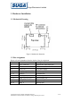
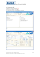
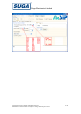
1.1 Mechanical Drawing
Figure1. Mechanical dimension
1.2 Pins Assignment
Please refer to the datasheet about the details of the pin assignment.
Pin# definition Description
1 ANT_WIFI_BT WIFI/BT RF input/output port
2, 13, 23 GND GND
14 VCC3.3V 3.3V power supply
3 ~ 8 SD_D[3:0], CMD, CLK SDIO data pins.
9 ~ 12 PCM_X PCM data pins
15 ~ 16 UART_TXD, RXD UART data pins
17, 19 PMU_EN, LNA_EN System enable pins
18 SYS_RST- System reset pin
20~22 IRQ_X Interrupt pins