
Instruction Manual


33
Réglages
Settings
Einstellungen
c) Schutzvorrichtung
Die Schutzvorrichtung funktioniert nur bei Spurreißer in
Arbeitstellung.
- Passive Schutzvorrichtung: Sicherheitsbolzen
Typ HM 10 x 90
Klasse 6.8.
Ein Ersatzbolzen ist auf
dem Arm vorgesehen.
d) Funktionsweise
- Belastung « ein Spurreißer hebt sich
- Entlastung « der andere Spurreißer senkt sich
- Belastung « der gesenkte Spurreißer hebt sich
- Entlastung « der andere Spurreißer senkt sich
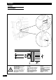
e) Einstellungen
• EINSTELLUNG DER SPURREIßER ANHAND DER SPUR
e x (n+1) V
D = -
22
DAbstand des Spurreißers bis zum ersten Schar in cm
n Reihenzahl der Drillmaschine
VVorderspur des Schleppers in cm
e Abstand der Schare in cm
D: Maß ab Außensäelement
• Beispiel: Drillmaschine 21 Reihen Abstand 14,3 cm,
Vorderspur des Schleppers 160 cm
<
14,3 x 22160
D = - = 77,3 cm
22
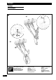
• Einstellung
- mit Hilfe der Kurbel Schraube lockern
- Arm unter gleichzeitiger Einstellung der
Scheibenneigung verlängern.
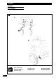
•
EINSTELLUNG DER SPURREIßER ANHAND DER
SC
HLEPPERMITTE
.
Der Abstand der letzten Saatlinie zum Spurreißerrad ist
gleich _ Arbeitsbreite plus _ Reihenabstand.
f) Anmerkungen
• Regelmäßig die Klemmung der Schraube (4m da N)
überprüfen.
• Den Sicherheitsschrauben-Typ beachten.
GB
c) Safety
The safety device only functions when the marker is in its
working position.
- Passive safety: HM 10X90 class 6.8 safety bolt .
A replacement bolt is provided on the
arm.
d) Operation
- Apply pressure « a marker is raised
- Release pressure « the other marker is lowered
- Apply pressure « the lowered marker is raised
- Release pressure « the other marker is lowered
e) Settings
• TRACK MARKER ADJUSTMENT.
e x (n+1) V
D = -
22
DDistance from the marker to the 1st coulter in cm
n Number of seed drill rows
VTractor front track in cm
e Coulter spacing in cm
D: Measurement to be made from outer coulter unit
• e.g. 21 row drill with 14.3 cm spacing, tractor front track =
160 cm
<
14.3 x 22160
D = - = 77.3 cm
22
•Adjustment
- loosen the screw with the crank
- extend the arm while adjusting the disc at the sam
•
CENTRAL MARKER ADJUSTMENT.
The distance between the last drilling line and the marker
disc is equal to half the working width plus half the gap
between the drilling line and the disc.
f) Notes
• Regularly check the tightening of the screw
(4m da N).
• Use the correct safety screw type.
c) Sécurité
La sécurité ne fonctionne que traceur en position travail.
- Sécurité passive :Boulon de sécurité
type HM 8 x 40 classe 6.8.
Un boulon de remplacement est
prévu sur le bras.
d) Fonctionnement
- Mettre la pression « un traceur se lève
- Relâcher la pression « l'autre traceur se baisse
- Mettre la pression « le traceur baissé se lève
- Relâcher la pression « l'autre traceur se baisse
e) Réglages
• RÉGLAGE DES TRACEURS À LA VOIE.
e x (n+1) V
D = -
22
D Distance du traceur à la 1ère botte en cm
n Nombre de rangs du semoir
V Voie avant du tracteur en cm
e Ecartement des bottes en cm
D : Cote à prendre à partir de l'élément semeur extérieur
• Exemple : semoir 21 rangs écartement 14.3 cm, voie
avant du tracteur 160 cm
14,3 x 22 160
D = - = 77,3 cm
22
• Réglage
- à l'aide de la manivelle, desserer la vis
- allonger le bras en réglant en même temps l'inclinaison
du disque.
• RÉGLAGE DES TRACEURS AU CENTRE.
La distance de la dernière ligne de semis au disque de
traceur est égale à une 1/2 largeur de travail, plus un 1/2
écartement.
f) Remarques
• Vérifier régulièrement le serrage de la vis (4m da N).
•Respecter le type de vis de sécurité.
F
D