
Product Manual
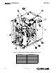
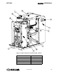
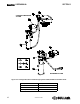
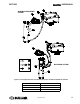
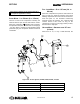
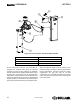
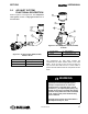
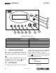
Table Of Contents
- Safety
- Description
- 2.1 Introduction
- 2.2 Compressor Component Description
- 2.3 Compressor Cooling And Lubrication System — Functional Description
- 2.4 Compressor Discharge System—Functional Description
- 2.5 Control System — Functional Description
- 2.6 Air Inlet System, Functional Description
- 2.7 Controller/Keypad
- 2.8 LCD Display
- 2.9 LED LIGHTS
- Specifications
- Installation
- Operation
- Maintenance
- 6.1 General
- 6.2 Maintenance After Initial 50 Hours of Operation
- 6.3 Maintenance Every 2000 Hours
- 6.4 Fluid Maintenance
- 6.5 Filter Maintenance
- 6.6 Air Filter Maintenance
- 6.7 Separator Maintenance
- 6.8 Belt Maintenance
- 6.9 Replacement and Alignment of Belt Pulleys
- 6.10 Hose Maintenance
- 6.11 TANK MOUNT PACKAGE MAINTENANCE
- 6.12 Troubleshooting – Introduction

SECTION 2 SHOPTEK
™
USER MANUAL
15
02250180-090 R00
START MODE - 0 TO 50 PSIG (0 TO 3.5 BAR)
There is no load on the compressor at startup, the
solenoid valve is open and the inlet valve is closed.
When the compressor (START) pad is pressed,
the separator tube pressure rises from 0 to 50 psig (0
- 3.4 bar). When it reaches its full operating speed
(maximum rpm), the compressor switches to the Full
Load Mode.
FULL LOAD MODE - 50 TO 127 PSIG (3.4 TO
8.8 BAR)
When the compressed air pressure rises above 50
psig (3.4 bar), the minimum pressure valve opens
allowing compressed air to flow into the service line.
From this point on, the Controller continuously
monitors the line air pressure. The solenoid valve
remains closed in this mode. As long as the
compressor is running at 127 psig (8.8 bar) or lower,
the inlet valve is fully open.
UNLOAD MODE - GREATER THAN 127 PSIG
(8.8 BAR)
When there is no, or only a small demand, the
Other pressure settings can be selected depending
on compressor application or rating.
Figure 2-5: Control System, ST400, ST500, ST700, 5-10 HP
1. Air Outlet 5. Separator Tube
2. Unload Solenoid Valve 6. Pressure Transducer
3. Air Inlet 7. Controller
4. Minimum Pressure/Check Valve 8. Check Valve