
Product Manual

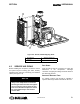
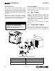

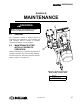

Table Of Contents
- Safety
- Description
- 2.1 Introduction
- 2.2 Compressor Component Description
- 2.3 Compressor Cooling And Lubrication System — Functional Description
- 2.4 Compressor Discharge System—Functional Description
- 2.5 Control System — Functional Description
- 2.6 Air Inlet System, Functional Description
- 2.7 Controller/Keypad
- 2.8 LCD Display
- 2.9 LED LIGHTS
- Specifications
- Installation
- Operation
- Maintenance
- 6.1 General
- 6.2 Maintenance After Initial 50 Hours of Operation
- 6.3 Maintenance Every 2000 Hours
- 6.4 Fluid Maintenance
- 6.5 Filter Maintenance
- 6.6 Air Filter Maintenance
- 6.7 Separator Maintenance
- 6.8 Belt Maintenance
- 6.9 Replacement and Alignment of Belt Pulleys
- 6.10 Hose Maintenance
- 6.11 TANK MOUNT PACKAGE MAINTENANCE
- 6.12 Troubleshooting – Introduction

SECTION 4 SHOPTEK
™
USER MANUAL
51
02250180-090 R00
4.3 SERVICE AIR PIPING
Before installing the compressor, review the service
air system’s layout including: pipe sizes, auxiliary
separator tube, drip legs, line filter(s), and isolation
valves (See Figure 4-3).
PIPE SIZING
Pipes should be sized as a minimum to match the
dimensions of the compressor’s discharge
connection. All piping and fittings should be rated for
the discharge pressure.
AUXILIARY RECEIVER TANK
An auxiliary receiver tank should be installed in
systems where large demand fluctuations will occur.
NOTE
Systems using both reciprocating and
rotary screw compressors must isolate
the two types from each other through the
use of a common receiver tank. Air lines
from each individual compressor should
be connected directly to the common
receiver tank.
Figure 4-2: ST1100, ST1500 Shipping Studs
1. Belt Guard 3. Shipping Studs (2)
2. Nut (2)