
Product Manual


SRHT 20-350 AC User Manual US-EN
02250246-084 R01
Subject to EAR. ECCN EAR99 and related export control restrictions.
61
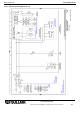
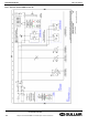
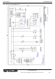
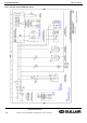
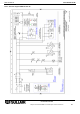
13.3 Electric diagrams
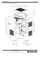
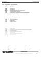
13.3.1 Electric diagrams – list of components
MC
:
Compressor
MV1
:
Condenser fan
MV2
:
Aftercooler fan
DMC14
:
DMC14 electronic instrument – air dryer control
BT1
:
Temperature probe – Dew Point
HPS
:
Pressure switch – compressor discharge side (HIGH PRESSURE)
LPS
:
Pressure switch – compressor suction side (LOW PRESSURE)
PV
:
Pressure switch – fan control
TS
:
Safety temperature switch
TSA
:
Aftercooler safety thermo switch
ELD
:
SULLIMAX drain
EVD
:
Timed condensate drain
S1
:
ON/OFF switch
KC1
:
TS Power contactor
NT1
:
Only air-cooled
NT2
:
Check the transformer connections with regard to the supply voltage
NT3
:
Jump, if not installed
NT4
:
Provided and cabled by the customer
NT5
:
Internal control
NT6
:
Time-controlled drain outlet (not used)
NT7
:
Only water-cooled
BN
=
BROWN
OR
=
ORANGE
BU
=
BLUE
RD
=
RED