30’ SUPERROLLER Operator’s Manual 30’ SUPERROLLER 30’ SUPERROLLER IMPORTANT THE OPERATOR IS RESPONSIBLE FOR ADJUSTING THE MACHINE SINCE MACHINE DOES NOT COME “FIELD READY” FROM FACTORY. CAUTION READ & UNDERSTAND OPERATOR’S MANUAL BEFORE USING MACHINE. See www.summersmfg.com for latest version of all Summers Operator’s Manuals. SUMMERS MANUFACTURING CO., INC. WEB SITE: www.summersmfg.com MADDOCK, NORTH DAKOTA 58348.................................... (701) 438-2855 DEVILS LAKE, NORTH DAKOTA 58301....
Warranty Summers warrants only products of its manufacture against operational failure caused by defective materials or workmanship which occur during normal use within 12 months from the date of purchase by the end user from Summers’ dealer.
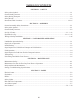
INTRODUCTION This manual provides the following information about your Summers Land Roller. SECTION CONTENTS Section 1 – SAFETY explains important safety precautions and familiarizes the Operator with the decals and their locations. Section 2 – ASSEMBLY includes step by step assembly instructions for your Summers Land Roller. Section 3 – LAND ROLLER OPERATION provides necessary information for the operation and adjustment of the machine. Section 4 – MAINTENANCE covers recommended mechanical maintenance.
TABLE OF CONTENTS SECTION 1 – SAFETY Safety-Alert Symbol......................................................................................................................................1-1 General Safety Practices................................................................................................................................1-1 Safety During Transport.................................................................................................................................
SECTION 1 - SAFETY SAFETY-ALERT SYMBOL This symbol is used to denote possible danger and care should be taken to prevent bodily injury. This symbol means: ATTENTION! BECOME ALERT! YOUR SAFETY IS INVOLVED! Definition of each Signal Word used in conjunction with the Safety-Alert symbol. DANGER indicates an imminently hazardous situation which, if not avoided, will result in death or serious injury. This signal word is to limited to the most extreme situations.
SECTION 1 - SAFETY SAFETY DURING TRANSPORT 1. Ability to safely operate the Summers Superroller is determined by both tractor horsepower and weight. The minimum tractor weight for operating this implement is 16,000 lbs. Minimum tractor engine horsepower is 125. Dual tires or single tires set at maximum width are required for safe operation of Land Roller. 2. ONLY TOW at a safe speed – 20 MPH MAXIMUM. Use caution when making corners or meeting traffic. 3.
SECTION 1 - SAFETY 3. PN 8Z0087 – DECAL FOR PINCH POINT HAZARD 4. PN 8Z0132 – SUPERROLLER ID DECAL 5.
SECTION 1 - SAFETY 6. PN 8Z0800 – AMBER REFLECTOR 7. PN 8Z0805 – RED-ORANGE REFLECTOR 8. PN 8Z0810 – RED REFLECTOR SAFETY LIGHT OPERATION The Summers Safety Light Kit is equipped with a 7 pin connector which meets SAE J560 specification. To protect 7 pin connector, store in dust cap (8K8067) when not attached to towing vehicle. On most towing vehicles WITHOUT brake lights: Amber lights will turn on with flashers or turn signals. Red lights will turn on with parking, road or field lights.
8Z0079 8Z0087 8Z0800 8Z0800 8Z0800 8Z0132 8Z0805 8Z0079 8Z0805 8Z0087 1-5 8Z0800 8Z0079 8Z0810 8Z0805 8Z0132 8Z0800 8Z0087 8Z0087 8Z0810 8Z0087 8Z0800 8Z0805 8Z0276 8/7/2012 8Z0810 9LR3042.
SECTION 1 - SAFETY 1-6
SECTION 2 - ASSEMBLY GENERAL ASSEMBLY SAFETY PRACTICES 1. READ AND UNDERSTAND Operator’s Manual before assembly of machine. 2. If machine is to be assembled INDOORS, check that exit door is a MINIMUM OF 11’ WIDE and a MINIMUM of tractor height. 3. Reference to “RIGHT” and “LEFT” is determined when machine IS VIEWED FROM THE REAR. 4. Reference to “FORWARD” means TOWARDS THE TRACTOR. 5. Reference to “REAR” means AWAY FROM THE TRACTOR.
SECTION 2 - ASSEMBLY GENERAL SAFETY PRACTICES YOU ARE RESPONSIBLE for the safe assembly of the machine. BLOCK UP ANY RAISED PART of the machine. Be sure machine is stable after blocking. DO NOT ALLOW CHILDREN or other unauthorized persons within the assembly area. ALWAYS INSPECT LIFTING CHAINS AND SLINGS for damage or wear. BE SURE LIFTING DEVICE IS RATED TO HANDLE THE WEIGHT.
SECTION 2 - ASSEMBLY Wing to Main Frame Installation MF1. Position Main Frame on a flat even surface. Set main frame on blocks or stands approximate 28 inches off ground in the locations shown in figure. 2 1 B B A A SUPPORT FOUR CORNERS OF FRAME WITH BLOCKS OR STANDS 3/15/2007 2 2-3 9LR3042.
SECTION 2 - ASSEMBLY MF2. Position 8P6115L as shown in the drawing below. 8P6115L weighs 1166 lbs, use extreme caution when positioning 8P6115L. Pay particular attention to the drawing to ensure that the proper wing is installed on the appropriate side. When positioned properly as shown in figure the correct orientation of the wing is determined by the mud scraper. The mud scraper should be positioned towards the rear of the machine as show in figure below.
SECTION 2 - ASSEMBLY Figure 2 2 1 8S3059 B 8S3059 B 8P6115R 8P6115L C 8P6030 B VIEW FROM BOTTOM 8S3059 8X0306 8X0095 8D0350 8X0260 A 8X0323 8P3910 8X0253 8P6230 8X0304 3/21/2007 2 MF4. Secure the pins with the hardware shown in the drawing. 8P6230 9LR3042.iam/-30 1 MF5. Repeat the above steps for 8P6115R. MF6. Install Dust Caps, PN 8S3059, into the locations shown in figure 2 and picture P-W2. MF7. Install 8P6230 as shown in figure 2.
SECTION 2 - ASSEMBLY Roller Installation R1. Clean Roller Pivot shafts R2. Elevate the wing frame and position roller under it. The wing frame will be free to pivot. Block the wing frame to control unexpected movement. Center roller in the wing frame and slowly lower the wing as shown in Figure 3. CAUTION: Each roller weighs 4285 lbs., block to prevent unexpected movement. Be careful when moving the rollers, use extreme caution when centering the rollers and lifting the wing frames.
SECTION 2 - ASSEMBLY R3. Install bearing with grease zerks towards the rear of the machine. Secure to bolt plates with hardware shown. Install reinforcement angles between the bottom attachment holes on in the inside of the bolt plate. As shown in Figure 4. Figure 4 2 1 B B A 8P5080 A A 8R8010 8P5080 MOUNTS ON ROLLER SIDE OF WING ATTACHMENT 8R8010 MOUNTS ON OUTSIDE OF WING ATTACHMENT 2 R 4. Install snap rings on each roller shaft.
SECTION 2 - ASSEMBLY Wheel and Pivot Arm Intallation. WP1. Locate 8P6110 and 8P6110S and install hub assemblies as shown in Figure 5. Secure hub assemblies with the hardware shown.
SECTION 2 - ASSEMBLY Figure 6 8P6215 8T1050 8T1050 5" X 10" TOWARDS TRACTOR B 8P6215 A 8D9108 8K9106 8T1055 5.5" X 10" 8T1055 8D9108 NOTE: WING AND ROLLERS (WHICH WERE PREVIOUSLY INSTALLED) HAVE BEEN EXCLUDED FROM THIS DRAWING FOR EASE OF REPRESENTATION. 8K9106 9/20/2010 9LR3042.iam/-75 WP9 Install the Lift cylinders as shown in Figure 6. Verify the correct location of the cylinders.
SECTION 2 - ASSEMBLY Hitch Installation H1. Assemble two 8P6220 to the Hitch. Secure the 8P6220’s to the hitch with 8P3910. Align hole in 8P3910 with the hole in 8P6220. Secure the pins with the hardware shown in Figure 7. Figure 7 2 1 B B 8X0304 LW 8X0323 FW 8X0253 LN 8X0095 8P3910 8P6000 A A 8P6220 4/2/2007 2 H2. 9LR3042.iam/-80 1 Position hitch as shown in Figure 8. Secure the Hitch to the main frame with the Hardware shown and as high on the main frame as possible.
1 Figure 8 2 8X0260 8X0306 B B C 2-11 A SECTION 2 - ASSEMBLY 8C1760 8D8522 ALL U-BOLTS SHOULD BE UNDER THE DOWN TUBE A NOTE: WINGS, DRUMS, WHEELS, PIVOT ARMS (WHICH WERE PREVIOUSLY INSTALLED) HAVE BEEN EXCLUDED FROM THIS DRAWING FOR EASE OF REPRESENTATION. 4/3/2007 2 9LR3042.
SECTION 2 - ASSEMBLY Pivot Cylinder Installation PC 1. Loosely attach 8P6210 (green) and 8P6211 (black) as shown in the drawing below. Please note the installation location of each part as they are different. Attach with the hardware shown in Figure 9. Figure 9 2 1 NOTE: WINGS, DRUMS, WHEELS, PIVOT ARMS (WHICH WERE PREVIOUSLY INSTALLED) HAVE BEEN EXCLUDED FROM THIS DRAWING FOR EASE OF REPRESENTATION.
SECTION 2 - ASSEMBLY Figure 10 2 1 DO NOT ATTACH ROD END OF CYLINDERS TO HITCH UNTIL CYLINDERS HAVE BEEN CYCLED 3 TIMES B B A A NOTE: WINGS, DRUMS, WHEELS, PIVOT ARMS (WHICH WERE PREVIOUSLY INSTALLED) HAVE BEEN EXCLUDED FROM THIS DRAWING FOR EASE OF REPRESENTATION. 4/3/2007 2 9LR3042.iam/-110 1 PC3. Location and final tightening of the hardware will be after the hydraulic cylinders have been cycled.
SECTION 2 - ASSEMBLY Hydraulic Installation H1. H2. H3. H4. H5. H6. H7. Install Hydraulic components as shown in Figure 12 provided. A. Leave enough slack at the hitch pivot to allow folding machine without stretching or pinching hydraulic hoses. B. Secure hoses with nylon ties and clamps provided. Do not over tighten clamps Block the hitch hydraulic cylinders so the rods can extend 32 inches without contacting any obstructions.
Figure 12 5-1/2" ROD SIDE TO 5" BASE SIDE - 8N3160 (160") = TRACTOR TO 8J5300 (TEES) 8N3348 (348") = TRACTOR TO 5-1/2" BASE & TRACTOR TO 5" ROD - 8N3432 (432") = TOP 8J5300 (TEE) TO ROD SIDE OF LEFT CYLINDER & BASE SIDE OF RIGHT CYLINDER - 8N3048 (48") = BOTTOM 8J5300 (TEE) TO BASE SIDE LEFT CYLINDER - 8N3060 (60") = TO ROD SIDE OF RIGHT CYLINDER - 8N3124 (124") = 8J6010 8J6010 2-15 SECTION 2 - ASSEMBLY 8J6010 8T1050 8D8500 8X0110 8T1055 8X0318 8J6010 TO 8J5300 (TEES) 8D8490 8J5510 TO 5" ROD SI
8X0143 8X0281 A 8L1060 8P5070 8K8030A 8P5070 8X0281 8K8075A 8D0340 8X0260 8X0306 B D 8K8095A 8S1120 8S1126 8K8210 8K8210 8K8210 8X0203 LIGHT WIRING SHOULD BE RUN WITH HYDRAULIC HOSE ALONG BOTTOM OF TUBE 8K8090A 8K8210 8A1155 8A1155 9/20/2010 8K8020 9LR3042.
SECTION 3 – OPERATION LAND ROLLER OPERATION SAFETY 1. READ AND UNDERSTAND Operator’s Manual before using machine. Review at least annually thereafter. 2. VERIFY all safety devices and shields are in place before using machine. 3. KEEP hands, feet, hair and clothing away from moving parts. 4. STOP engine, place all controls in neutral, set parking brake, remove ignition key and wait for all moving parts to stop before servicing, adjusting, maintaining or unplugging. 5.
SECTION 3 – OPERATION INITIAL HOOKUP: 1. Make tractor to hitch connection with locking draw pin and safety chain. 2. Retract jack and rotate into storage position. 3. Plug Hitch Cylinder hoses into desired tractor outlet, adjust hydraulic flow rate to 35% of maximum. Insure that tips and couplers are CLEAN. 4. Plug Lift Cylinder hoses into desired tractor outlet, adjust hydraulic flow rate to 35% of maximum. 5. Connect safety Light Kit wiring harness to 7 pin receptacle. 6.
SECTION 3 – OPERATION STEPS REQUIRED TO UNFOLD FROM TRANSPORT TO FIELD POSITION: 1. WARNING: Land Roller must be attached directly to tractor drawbar and not an intermediate towed vehicle or implement. Loss of control could result causing serious injury or death to you or others. Never tow this implement with less than an 16,000 lb. vehicle 2. Ability to safely operate the Summers Land Roller is determined by both tractor horsepower and weight.
SECTION 3 – OPERATION LAND ROLLER FIELD OPERATION: 1. If Land Roller is in Transport Position, follow “Steps Required to Unfold Land Roller from Transport to Field Position”, page 3-3. 2. Choose an operating speed which achieves desired results. Operating at over 7 MPH will decrease effectiveness and increase chance of immovable rocks denting roller tube. Denting of roller tube is NOT covered by warranty. STEPS REQUIRED TO FOLD FROM FIELD TO TRANSPORT POSITION: 1.
SECTION 3 – OPERATION TRANSPORTING LAND ROLLER: 1. If Land Roller is in Field Position, follow “Steps Required to Fold Land Roller from Field to Transport Position”, page 3-4. 2. Ability to safely operate the Summers Superroller is determined by both tractor horsepower and weight. The minimum tractor weight for operating this implement is 16,000 lbs. Minimum tractor engine horsepower is 125. Dual tires or single tires set at maximum width are required for safe operation of Land Roller. 3.
SECTION 3 – OPERATION UNHOOKING LAND ROLLER FROM TRACTOR IN FIELD POSITION: 1. NEVER unhook Land Roller if positioned hydraulically between Field and Transport Position. 2. Choose a firm level surface. 3. With Land Roller in Field Position; shut off tractor, engage parking brake and relieve hydraulic pressure by cycling remote lever. 4. Block rollers to prevent movement after hitch pin is removed. 5. Check that hitch pin is not bound with sideways or front to back pressure.
SECTION 4 – MAINTENANCE MAINTENANCE SAFETY 1. STOP engine, place all controls in neutral, set parking brake, remove ignition key and wait for all moving parts to stop before servicing, adjusting or maintaining. 2. BE CAREFUL when working around high pressure hydraulic system. 3. ALWAYS make sure that Land Roller is lowered into field position, it is blocked to prevent movement and pressure is relieved from hydraulic circuits before servicing. 4. USE EXTREME CARE when making adjustments. 5.
SECTION 4 – MAINTENANCE STORAGE 1. Follow steps outlined in “UNHOOKING LAND ROLLER FROM TRACTOR IN FIELD POSITION”. 2. Clean and remove all excessive dirt and grease from Land Roller. 3. Grease all zerks. 4. To prevent rusting, repaint any areas that have been worn, chipped or scratched. 5. Apply grease* to any exposed part of cylinder shafts. *NOTE: Before returning Land Roller into service, all grease must be removed from cylinder shafts to prevent damage to seals.
SECTION 5 – PARTS REMEMBER TO BRING YOUR OWNER REGISTER INFORMATION LOCATED AT THE BEGINNING OF THIS MANUAL WHEN ORDERING PARTS (SERIAL NUMBER IS LOCATED BY THE FRONT OF THE HITCH).
8P5070 8P6000 8T1050 8P3910 8X0323 8P6110S 8X0095 8X0304 8P5070 8X0253 B 8D8522 8P6030 5-2 A 8D0350 8S3059 8P6215 8X0323 8P6115L 8X0095 8X0304 8X0253 8P3910 8K9106 8K1105S 8T1055 8D0350 8K9106 8P6110 8T4100 8T3640 10/9/2012 9LR3042.
5-1/2" ROD SIDE TO 5" BASE SIDE - 8N3160 (160") = TRACTOR TO 8J5300 (TEES) 8N3348 (348") = TRACTOR TO 5-1/2" BASE & TRACTOR TO 5" ROD - 8N3432 (432") = TOP 8J5300 (TEE) TO ROD SIDE OF LEFT CYLINDER & BASE SIDE OF RIGHT CYLINDER - 8N3048 (48") = BOTTOM 8J5300 (TEE) TO BASE SIDE LEFT CYLINDER - 8N3060 (60") = TO ROD SIDE OF RIGHT CYLINDER - 8N3124 (124") = 8J6010 8J6010 5-3 SECTION 5 – PARTS 8J6010 8T1050 8D8500 8X0110 8T1055 8X0318 8J6010 TO 8J5300 (TEES) 8D8490 8J5510 TO 5" ROD SIDE 8J5300 TO 5-
2 1 B B SECTION 5 – PARTS 5-4 8P5080 8R8010 A A 8P4215 8X0306 8X0265 8R8005 8X0111 4/3/2007 2 9LR3042.
8X0139 8K8070B 8X0143 8X0281 A 8L1060 8P5070 8K8030A 8P5070 8X0281 8K8075A 8D0340 8X0260 8X0306 B SECTION 5 – PARTS 5-5 C LIGHT WIRING SHOULD BE ZIP TIED TO SIDE OF TUBE D 8K8095A 8S1120 8S1126 8K8210 8K8210 8K8210 8X0203 LIGHT WIRING SHOULD BE RUN WITH HYDRAULIC HOSE ALONG BOTTOM OF TUBE 8K8090A 8K8210 8A1155 8A1155 9/20/2010 8K8020 9LR3042.
HUB AND AXLE COMPONENTS Assembly Notes: A. Before towing machine, pack wheel bearings and fill 1/2 of hub cavity with high quality bearing grease. B. Tighten axle nut to 45 ft.-lbs, loosen nut until first slot is aligned with hole in axle, install cotter pin and bend to retain. Legend: SMC INDUSTRY 2.
SUMMERS MFG. CO., INC. 3/21/12 INSTALLATION AND OPERATION INSTRUCTIONS FOR 8K1800 ACRE METER FOR SUPERROLLER 1. If Roller Shaft is not tapped, weld ½”-20 UNF nut at center of left pivot shaft of middle roller. Position external taper of nut toward shaft. Insure that threads are not damaged by weld heat or spatter. Allow weld to cool. 2. Attach Acre Meter with ½” lock washer. Tighten to 260-390 in-lbs. * For accurate logging of acres, it is important that meter is mounted concentrically on roller shaft.
Stock Code 8A1155 8A4048 8A4050 8A4052 8C0270 8C0432 8C1760 8C1780 8D0330 8D0340 8D0350 8D0720 8D0722 8D0724 8D0730 8D2440 8D2460 8D2470 8D3212 8D5314 8D8490 8D8500 8D8522 8D9102 8D9108 8G2284 8G2285 8J5100 8J5110 8J5200 8J5300 8J5310 8J5500 8J5510 8J5520 8J5600 8J5620 8J5680 8J5690 8J5700 8J5710 8J6010 8J6020 8J6060 8J7000 8J7040 8J7116 8J7216 8J7232 8K1105S 8K5350 8K5515 8K7020 8K7028 8K7042 8K7111 8K7113 8K7117 Description U-BOLT 3/8 X 6-1/16 X 5” SQ NYLON TIE .18 X 11” NYLON TIE .
Stock Code 8N4120 8N4138 8N4198 8N4216 8N4228 8N4546 8N4624 8P3010 8P3500 8P3900 8P3910 8P4215 8P5070 8P5080 8P6000 8P6020P 8P6030 8P6100 8P6100S 8P6115L 8P6115R 8P6210 8P6211 8P6215 8P6220 8P6230 8R6808 8R6810 8R8005 8R8010 8S1120 8S1124 8S1126 8S2980 8S2990 8S3059 8T1050 8T1055 8T1150 8T1155 8T2986 8T3640 8T4100 8T4350 8T5345 8X0000 8X0000B 8X0001 8X0002 8X0003 8X0004 8X0005 8X0006 8X0007 8X0007B 8X0008 8X0009 8X0010 Description 1/2X 120”HYD HOSE#10FJX3000PSI 1/2X 138”HYD HOSE#10FJX3000PSI 1/2X 198”HYD H
Stock Code 8X0113 8X0114 8X0115 8X0115A 8X0115B 8X0116 8X0117 8X0118 8X0118A 8X0119 8X0120 8X0121 8X0122 8X0123 8X0125 8X0130 8X0132 8X0133 8X0138 8X0139 8X0140 8X0143 8X0144 8X0145 8X0149 8X0201 8X0202 8X0203 8X0204 8X0205 8X0210 8X0211 8X0212 8X0218 8X0220 8X0222 8X0223 8X0232 8X0234 8X0240 8X0242 8X0246 8X0250 8X0251 8X0253 8X0256 8X0259 8X0260 8X0261 8X0268 8X0269 8X0277 8X0278 8X0280 8X0281 8X0283 8X0284 Description BOLT 3/4-10NC X 5” GR5 ZDI BOLT 3/4-10NC X 3” GR5 ZDI BOLT 3/4-10NC X 3-1/2” GR5 ZDI B
History of Summers Manufacturing Co., Inc. 1965 – Summers Manufacturing is founded by Harley Summers, who purchases patent rights for Goebel truck and pickup hoists from the Goebel Brothers of Lehr, ND. These hoists, produced in Harley Summers’ blacksmith shop the first year, were distributed nationwide by a Cincinnati, Ohio, dealer. With increasing sales, the company soon outgrows the small shop. Summers wins the Herman harrow contract, beginning the company’s Herman culti-harrow line.
Model 700 Rock Picker Superrollers Superchisel Coulter-Chisel Disk-Chisel Hydraulic Fold Coil Packer & Hydraulic Fold Rolling Chopper Mounted Harrows Rolling Choppers Superharrow Plus & Superharrow 2650 Diamond Disk & 2510 DT Supercoulter Plus © Copyright 2013 Summers Manufacturing Co., Inc. All Rights Reserved Rolling Baskets Ultra & Ultimate NT Supersprayer 11-1-12 To find a dealer near you check out our website - www.summersmfg.