41’, 45’ & 50’ SUPERROLLER Operator’s Manual 41’, 45’ & 50’ HYDRAULIC WING FOLD 41’, 45’ & 50’ SUPERROLLER SUPERROLLER IMPORTANT THE OPERATOR IS RESPONSIBLE FOR ADJUSTING THE MACHINE SINCE MACHINE DOES NOT COME “FIELD READY” FROM FACTORY. CAUTION READ & UNDERSTAND OPERATOR’S MANUAL BEFORE USING MACHINE. See www.summersmfg.com for latest version of all Summers Operator’s Manuals. SUMMERS MANUFACTURING CO., INC. WEB SITE: www.summersmfg.com MADDOCK, NORTH DAKOTA 58348................................
Warranty Summers warrants only products of its manufacture against operational failure caused by defective materials or workmanship which occur during normal use within 12 months from the date of purchase by the end user from Summers’ dealer.
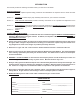
INTRODUCTION This manual provides the following information about your Summers Land Roller. SECTION CONTENTS Section 1 – SAFETY explains important safety precautions and familiarizes the Operator with the decals and their locations. Section 2 – ASSEMBLY includes step by step assembly instructions for your Summers Land Roller. Section 3 – LAND ROLLER OPERATION provides necessary information for the operation and adjustment of the machine.
TABLE OF CONTENTS SECTION 1 – SAFETY Safety-Alert Symbol.......................................................................................................................1-1 General Safety Practices...............................................................................................................1-1 Safety During Transport................................................................................................................1-2 Safety Decals.........................................
SECTION 1 - SAFETY SAFETY-ALERT SYMBOL This symbol is used to denote possible danger and care should be taken to prevent bodily injury. This symbol means: ATTENTION! BECOME ALERT! YOUR SAFETY IS INVOLVED! Definition of each Signal Word used in conjunction with the Safety-Alert symbol. DANGER WARNING CAUTION indicates an imminently hazardous situation which, if not avoided, will result in death or serious injury. This signal word is to limited to the most extreme situations.
SECTION 1 - SAFETY SAFETY DURING TRANSPORT 1. Ability to safely operate the Summers Superroller is determined by both tractor horsepower and weight. The minimum tractor weight for operating this implement is 16,000 lbs. Minimum tractor engine horsepower is 160. Dual tires or single tires set at maximum width are required for safe operation of Land Roller. 2. ONLY TOW at a safe speed – 20 MPH MAXIMUM. Use caution when making corners and meeting traffic. 3.
SECTION 1 - SAFETY 3. PN 8Z0086 – ELECTRICUTION DANGER 4. PN 8Z0087 – DECAL FOR PINCH POINT HAZARD 5.
SECTION 1 - SAFETY 6. PN 8Z0106 – DECAL FOR LANDROLLER DANGER 7.
SECTION 1 - SAFETY 8. PN 8Z0276 – DECAL FOR GENERAL CAUTION 9. PN 8Z0344 – DECAL FOR WING DANGER 10. PN 8Z0346 – DECAL FOR ELECTRICUTION DANGER 11. PN 8Z0800 – AMBER REFLECTOR 12. PN 8Z0805 – RED-ORANGE REFLECTOR 13. PN 8Z0810 – RED REFLECTOR SAFETY LIGHT OPERATION The Summers Safety Light Kit is equipped with a 7 pin connector. To protect 7 pin connector, store in dust cap (8K8067) when not attached to towing vehicle.
SECTION 1 - SAFETY 1-6
SECTION 2 - ASSEMBLY GENERAL ASSEMBLY SAFETY PRACTICES 1. READ AND UNDERSTAND Operator’s Manual before assembly of machine. 2. Machine should be assembled in a horizontal (field) position only. 3. If machine is to be assembled INDOORS, check that exit door is: MACHINE WIDTH 41’ 45’ 50’ MINIMUM DOOR WIDTH MINIMUM DOOR HEIGHT 17’2” 14’2” 17’2” 15’2” 16’10” 16’2” 4. Reference to “RIGHT” and “LEFT” is determined when machine IS VIEWED FROM THE REAR. 5. Reference to “FORWARD” means TOWARDS THE TRACTOR. 6.
SECTION 2 - ASSEMBLY GENERAL SAFETY PRACTICES YOU ARE RESPONSIBLE for the safe assembly of the machine. BLOCK UP ANY RAISED PART of the machine. Be sure machine is stable after blocking. DO NOT ALLOW CHILDREN or other unauthorized persons within the assembly area. ALWAYS INSPECT LIFTING CHAINS AND SLINGS for damage or wear. BE SURE LIFTING DEVICE IS RATED TO HANDLE THE WEIGHT.
SECTION 2 - ASSEMBLY CENTER ROLLER INSTALLATION CR1. Position Center Roller on a firm, level surface. CAUTION: Each Roller weighs up to 4285#, block to prevent unexpected movement. CR2. Clean Roller pivot shafts. CR3. Lower Center Frame over Roller. The Center weighs 2424#, use extreme caution when positioning over Roller. CR4. Install bearings with grease zerks toward rear of machine. Apply anti-seize to shaft. Secure to bolt plates with 3/4” x 2-3/4” bolts, lockwashers and locknuts.
SECTION 2 - ASSEMBLY SET-UP OF HITCH AND CENTER FRAMES F1. Install two outside hub assemblies ONLY. Apply good quality anti-seize to axles before installation. Retain axles into receiver tube with 1/2” x 4-1/2” bolt and locknut. Install Wheel and Tire assemblies on outside hubs. Torque wheel nuts to 240 FT-LB. F2. Lower tires to ground. Align Hitch to Center. Connect with 2” x 11” pins. Secure pins with 5/8” x 5” bolts, washers and locknuts. F3.
SECTION 2 - ASSEMBLY SECTION 2 - ASSEMBLY SET-UP OF TRANSPORT REST 8C1760 3/4 X 8-1/16 X 6" TR1. Install Transport Rest components as shown. a. Do not tighten 8X0111A Set Bolts. These will be adjusted after Wings are installed b. Position front 8P5060 against Upright. Tighten U-bolt. Position and hand tighten rear 8P5060. Insert 1” x 5” bolts through front 8P5060, loop end of Safety Chains and rear 8P5060. Fully tighten 1” locknut and U-bolt for rear 8P5060. c.
SECTION 2 - ASSEMBLY SECTION 2 - ASSEMBLY CENTER LIFT CYLINDER 8C0532 8X0418 8X0327 1 1/4" FW 8K1620 8C0532 8J6010 3/4-16ORB X #6JIC(M) 90° ADP 8J5620 3/4" X #6 JIC (F-SW) 8J5298 #6 JIC(M+M+F-SW) TEE 8J7250 8J6002 TEE #6JIC(M) X 9/16ORB 8J5690 3/4-16X3/4-16 ORB M-SW 90° UNION 8J7116 * 8J5510 3/4" ORB X #6 JIC(M) 8J5510 3/4" ORB X #6 JIC(M) 8J7000 VALVE 9/16ORB 8J5680 3/4"X3/4" UNION 8N3060 3/8"X60" 8J6000 9/16ORB X #6JIC(M) 90° 8J5500 9/16" X #6 JIC(M) 8J6004 9/16"X#6(M) RUN-T 8J7040 THERM
SECTION 2 - ASSEMBLY H1. Install Hydraulic components as shown. a. Leave enough slack at hitch pivot to allow folding machine without stretching or pinching hydraulic hoses. b. Secure with nylon ties and clamps provided. Do not over tighten clamps. H2. Block hydraulic cylinders so rods can extend 32” without contacting any obstructions. Fully extend and retract cylinders 3 times to insure all air is purged from system. H3.
SECTION 2 - ASSEMBLY WING INSTALLATION 8D9108 1/4 X 2" RP 8L0252 8K9106 8X0316 1" FW 8C0532 8P3500 8S3059 2.067" CAPLUG 8X0282 8X0260 3/4" N 8X0095 5/8" X 5" 8P3910 8X0323 5/8" FW 8X0253 NY-LOCK 5/8"-11NC 8P3500 8T3300 8X0306 3/4" LW 8X0304 5/8" LW 8X0281 NY-LOCK 1" 8P5070 8D0340 3/4 X 4 X 7-3/4" 8X0143 1X5" 41' 8P4067 - LEFT 8P4077 - RIGHT 12/31/2009 45' 8P4070 - LEFT (SHOWN) 8P4080 - RIGHT 50' 8P4075 - LEFT 8P4085 - RIGHT 9LR4542.iam/WING W1.
SECTION 2 - ASSEMBLY P-W2 P-W1 DO NOT OVER TIGHTEN. PIVOT BOLT MUST BE FREE TO ROTATE.
SECTION 2 - ASSEMBLY WING ROLLER INSTALLATION 8P3010 PLUG 2-1/2" NPT STAMPED H LOCATION. POSITION TOWARDS MACHINE CENTER, NEXT TO HINGE. 8R8010 8X0364 2-1/2" FW (AS REQUIRED ON OUTSIDE WING SO WING ROLLER AND WING STOP CONTACT CENTER IN TRANSPORT) 8X0265 3/4" LN 8P4213 - 41' MACHINE WIDTH 8P4215 - 45' MACHINE WIDTH 8P4205 - 50' MACHINE WIDTH 8P5080 8X0306 3/4" LW 12/11/2013 8X0111A 3/4" X 2-3/4" 8R8005 SNAP RING 9LR4542.iam/ROLLER_INSTALL WR1. Clean Roller pivot shafts. WR2.
SECTION 2 - ASSEMBLY FOLD AND UNFOLD LAND ROLLER WITH ROLLERS INSTALLED: 1. See Page 3-5 for STEPS REQUIRED TO FOLD FROM FIELD TO TRANSPORT POSITION. Follow these steps. 2. See Page 3-3 for STEPS REQUIRED TO UNFOLD FROM TRANSPORT TO FIELD POSITION. Follow these steps. NOTE: To prevent rust, spray paint Bearings and Roller Shaft after assembly is complete.
SECTION 2 - ASSEMBLY SAFETY LIGHT & DECAL INSTALLATION 8K8030A MODULE-ENHANCER 8S1120 8S1126 8X0164 #10 X 3" SCREW 8X1120 CRG 3/8"x2" 8S1124 (2" USED ON UPRIGHT) 8K8090A 8S2990 HOSE CLMP 8X0021A 5/16 X 1" 8X0211 5/16" FN 8X0202 3/8" LN E 8A1155 3/8X6-1/16X5" 8X0205 #10 NUT DETAIL A SCALE 1 / 17 8X0303 1/2" LW 8T2988 8X0202 3/8" LN 8X1110 CRG 3/8"x1" A B 8K8075A EXTENSION HARNESS (1" USED ON CENTER AND UPRIGHT SUPPORTS) DETAIL D SCALE 1 / 17 D 8X0203 3/8" FN 8K8202 8D8500 8X0000 1/4 X
SECTION 2 - ASSEMBLY 2-13
SECTION 2 - ASSEMBLY ASSEMBLY COMPLETE 2-14
SECTION 3 – OPERATION LAND ROLLER OPERATION SAFETY 1. READ AND UNDERSTAND Operator’s Manual before using machine. Review at least annually thereafter. 2. VERIFY that all safety devices and shields are in place before using machine. 3. KEEP hands, feet, hair and clothing away from moving parts. 4. STOP engine, place all controls in neutral, set parking brake, remove ignition key and wait for all moving parts to stop before servicing, adjusting, maintaining or unplugging. 5.
SECTION 3 – OPERATION INITIAL HOOKUP: 1. Make tractor to hitch connection with locking draw pin and safety chain. 2. Retract jack and rotate into storage position. 3. Insure that tips and couplers are CLEAN. Plug Center Tilt Cylinder hoses into desired tractor outlet. Adjust hydraulic flow rate to 35% of maximum. 4. Plug Wing Lift Cylinder hoses into desired tractor outlet. Adjust hydraulic flow rate to 35% of maximum. 5. Connect safety Light Kit wiring harness to 7 pin receptacle. 6.
SECTION 3 – OPERATION STEPS REQUIRED TO UNFOLD FROM TRANSPORT TO FIELD POSITION: 1. WARNING: Land Roller must be attached directly to tractor drawbar and not an intermediate towed vehicle or implement. Loss of control could result causing serious injury or death to you or others. 2. Ability to safely operate the Summers Land Roller is determined by both tractor horsepower and weight. The minimum tractor weight for operating this implement is 16,000 lb. Minimum tractor engine horsepower is 160.
SECTION 3 – OPERATION 6. Operate tractor hydraulics from operator station only. Do not allow anyone to stand near Land Roller when folding or unfolding. Do not raise or lower Land Roller when implement is moving. 7. Fully extend Center Tilt Cylinder, Wings will rotate rearward, maintain hydraulic pressure an additional 5 seconds to insure cylinder and hoses are fully charged with oil. Retract Center Tilt cylinder approximately 1/2”. 8. Lower wings with caution by fully extending Wing Lift cylinders.
SECTION 3 – OPERATION LAND ROLLER FIELD OPERATION: 1. If Land Roller is in Transport Position, follow “Steps Required to Unfold Land Roller from Transport to Field Position”, page 3-3. 2. When in field position, place Center Tilt Cylinder remote into float position. This will allow rollers to self level. 3. Choose an operating speed which achieves desired results. Operating at over 7 MPH will decrease effectiveness and increase chance of immovable rocks denting roller tube.
SECTION 3 – OPERATION PROCEDURE TO ADJUST HYDRAULIC CYLINDER ATTACH EYE BOLTS: Refer to the drawing and photo on next page before adjusting Attachment Eye Bolts. Follow these steps: 1. Adjust Wing Lift Cylinder Eye Bolts FIRST. Adjust Eye Bolts so Wing Stop and Roller rest on Center contact areas when Wing Lift Cylinder is fully retracted. a. If Wing does not contact Center, lower wing, relieve hydraulic pressure and adjust Eye Bolt towards machine center line. b.
SECTION 3 – OPERATION 3-7
SECTION 3 – OPERATION TRANSPORTING LAND ROLLER: 1. If Land Roller is in Field Position, follow “Steps Required to Fold Land Roller from Field to Transport Position”, page 3-5. 2. Ability to safely operate the Summers Superroller is determined by both tractor horsepower and weight. The minimum tractor weight for operating this implement is 16,000 lbs. Minimum tractor engine horsepower is 160. Dual tires or single tires set at maximum width are required for safe operation of Land Roller. 3.
SECTION 3 – OPERATION UNHOOKING LAND ROLLER FROM TRACTOR IN FIELD POSITION (HIGHLY RECOMMENDED): 1. WARNING: It is highly recommended to unhook Land Roller in Field Position ONLY. unhook Land Roller if positioned hydraulically between Field and Transport Position. NEVER 2. Choose a firm level surface with enough open area that will allow unfolding Land Roller without contacting any obstructions.
SECTION 3 – OPERATION C. Block tires to prevent movement after hitch pin is removed. D. Check that hitch pin is not bound with side or front to back pressure. If hitch pin is not free, carefully reposition tractor. E. With hitch pin free, if hitch piece lifts up on tractor drawbar, negative tongue weight exists. DO NOT UNHOOK LAND ROLLER WITH NEGATIVE TONGUE WEIGHT.
SECTION 4 – MAINTENANCE MAINTENANCE SAFETY 1. STOP engine, place all controls in neutral, set parking brake, remove ignition key and wait for all moving parts to stop before servicing, adjusting or maintaining. 2. BE CAREFUL when working around high pressure hydraulic system. 3. ALWAYS make sure that Land Roller is lowered into field position (cylinders extended), it is blocked to prevent movement and pressure is relieved from hydraulic circuits before servicing. 4.
SECTION 4 – MAINTENANCE STORAGE 1. Follow steps outlined in “UNHOOKING LAND ROLLER FROM TRACTOR IN FIELD POSITION”. 2. Clean and remove all excessive dirt and grease from Land Roller. 3. Grease all zerks. 4. To prevent rusting, repaint any areas that have been worn, chipped or scratched. 5. Apply grease* to any exposed part of cylinder shafts. *NOTE: Before returning Land Roller into service, all grease must be removed from cylinder shafts to prevent damage to seals.
SECTION 4 – MAINTENANCE PROPER BOLT USE DO NOT use these values if a different torque value or tightening procedure is given for a specific application. Torque values listed are for general use only. Check tightness of fasteners periodically.
SECTION 4 – MAINTENANCE NOTES 4-4
SECTION 5 – PARTS OWNER REGISTER INFORMATION, LOCATED AT THE BEGINNING OF THIS MANUAL, MAY BE NEEDED WHEN ORDERING PARTS (SERIAL NUMBER IS LOCATED AT THE FRONT OF HITCH).
8X0286 1 1/2" JN 8X0304 5/8" LW 8X0250 5/8" N 8P7240 8X0286 1 1/2" JN 8X0315 1-1/2" LW 8X0721 ZERK 5/16"-24TPI 8P4020 (36") 8P4040 (42") 8X0285 1 1/2" N 8X0286 1 1/2" JN 41' & 45' ONLY 8L4628 B 8X0285 1 1/2" N 5-2 8X0000 1/4 X 3/4" 8X0315 1-1/2" LW 8X0110 3/4 X 1.
8C1760 3/4 X 8-1/16 X 6" 8X0260 3/4" N 8P5040 8P5060 L 3.5 x 3 x 1/2 8X0306 3/4" LW 8X0306 3/4" LW 8X0260 3/4" N 8R8005 SNAP RING (2X EACH SIDE) 8P5000 8D2440 8P5020 8C1760 3/4 X 8-1/16 X 6" 5-3 8X0260 3/4" N 8X0111A 3/4" X 2-3/4" 8X0306 3/4" LW 8X0259 3/4" JN 8X0281 NY-LOCK 1" 8C1760 3/4 X 8-1/16 X 6" 8P5060 L 3.5 x 3 x 1/2 8C1760 3/4 X 8-1/16 X 6" 8X0143 1X5" 1/14/2014 9LR4542.
CENTER LIFT CYLINDER 8X0327 1 1/4" FW 8K1620 8C0532 8J6010 3/4-16ORB X #6JIC(M) 90° ADP 8J5620 3/4" X #6 JIC (F-SW) 8J5298 #6 JIC(M+M+F-SW) TEE 8J7250 8J5510 3/4" ORB X #6 JIC(M) 8J5510 3/4" ORB X #6 JIC(M) 8J7000 VALVE 9/16ORB 8J7040 THERMAL RELIEF 8A1954 1/4"X18" 8J5300 #6 JIC(M) TEE 8S2990 HOSE CLMP 8J7116 * 8J5690 3/4-16X3/4-16 ORB M-SW 90° UNION *FREE FLOW ARROW MUST POINT TOWARDS 8J5690 90° ELBOW 8X1130 CRG 3/8"x3" 8G2285 GREEN CENTER TILT 8N3348 3/8"X348" 8X0304 5/8" LW 8X0250 5/8" N
8D9108 1/4 X 2" RP 8L0252 8K9106 8X0316 1" FW 8C0532 8P3500 8S3059 2.067" CAPLUG 8X0282 8X0095 5/8" X 5" 8T3300 SECTION 5 – PARTS 8X0260 3/4" N 8P3500 8X0306 3/4" LW 5-5 8P3910 8X0323 5/8" FW 8X0253 NY-LOCK 5/8"-11NC 8X0304 5/8" LW 8X0281 NY-LOCK 1" 8P5070 8D0340 3/4 X 4-1/16 X 7-3/4" 8X0143 1X5" 41' 8P4067 - LEFT 8P4077 - RIGHT 12/11/2013 45' 8P4070 - LEFT (SHOWN) 8P4080 - RIGHT 9LR4542.
8P3010 PLUG 2-1/2" NPT 8R8010 8X0364 2-1/2" FW (AS REQUIRED ON OUTSIDE WING SO WING ROLLER AND WING STOP CONTACT CENTER IN TRANSPORT) 8P4213 - 41' MACHINE WIDTH 8P4215 - 45' MACHINE WIDTH 8P4205 - 50' MACHINE WIDTH 8X0265 3/4" LN 8P5080 8X0306 3/4" LW 12/11/2013 8X0111A 3/4" X 2-3/4" 8R8005 SNAP RING 9LR4542.iam/ROLLER_INSTALL SECTION 5 – PARTS 5-6 STAMPED H LOCATION. POSITION TOWARDS MACHINE CENTER, NEXT TO HINGE.
8K8030A MODULE-ENHANCER 8S1120 8S1126 8X0164 #10 X 3" SCREW 8X1120 CRG 3/8"x2" 8S1124 (2" USED ON UPRIGHT) 8K8090A 8S2990 HOSE CLMP 8X0021A 5/16 X 1" 8X0211 5/16" FN 8X0202 3/8" LN E 8A1155 3/8X6-1/16X5" 8X0205 #10 NUT DETAIL A SCALE 1 / 17 8X0303 1/2" LW 8T2988 8X0202 3/8" LN 8X1110 CRG 3/8"x1" B DETAIL D SCALE 1 / 17 D 5-7 8X0203 3/8" FN 8K8202 8D8500 8X0000 1/4 X 3/4" 8K8067 8A4048 11" TIE 8X0110 3/4 X 1.
HUB AND AXLE COMPONENTS Assembly Notes: A. Before towing machine, pack wheel bearings and fill 1/2 of hub cavity with high quality bearing grease. B. Tighten axle nut to 45 ft.-lbs, loosen nut until first slot is aligned with hole in axle, install cotter pin and bend to retain. 5-8 HUB H413 H511 H517 H611 H614 LR HD812 1. SEAL 2. INNER BEARING 3. INNER RACE 4. OUTER 5. HUB ASSY RACE 8D5120 8D5117 8D5336 8D5330 M6527850 SE11 LM67048 LM67010 LM11910 H413 6. WHEEL STUD 8. 7.
SUMMERS MFG. CO., INC. 3/21/12 INSTALLATION AND OPERATION INSTRUCTIONS FOR 8K1800 ACRE METER FOR SUPERROLLER 1. If Roller Shaft is not tapped, weld ½”-20 UNF nut at center of left pivot shaft of middle roller. Position external taper of nut toward shaft. Insure that threads are not damaged by weld heat or spatter. Allow weld to cool. 2. Attach Acre Meter with ½” lock washer. Tighten to 260-390 in-lbs. * For accurate logging of acres, it is important that meter is mounted concentrically on roller shaft.
Stock Code 8A1155 8A4048 8A4050 8A4052 8C0532 8C0535 8C1760 8D0340 8D0720 8D0722 8D0730 8D2440 8D2470 8D3212 8D5312 8D5319 8D8490 8D8500 8D8521 8D8523 8D9108 8G2284 8G2285 8J5100 8J5300 8J5500 8J5510 8J5600 8J5620 8J5680 8J5690 8J5700 8J6000 8J6002 8J6004 8J6010 8J6060 8J7000 8J7040 8J7116 8J7216 8J7232 8K1105 8K1620 8K7020 8K7028 8K7111 8K7113 8K7117 8K7118 8K7120 8K7122 8K7123 8K7127 8K7128 8K7130 8K7132 8K7150 Description U-BOLT 3/8 X 6-1/16 X 5” SQ NYLON TIE .18 X 11” NYLON TIE .30 X 8-7/8” NYLON TIE .
Stock Code 8X0021B 8X0022 8X0023 8X0030 8X0031 8X0033 8X0034 8X0036 8X0038 8X0041 8X0044 8X0045 8X0046 8X0047 8X0061 8X0062 8X0063 8X0066 8X0067 8X0068 8X0069 8X0070 8X0072 8X0073 8X0074 8X0075 8X0076 8X0077 8X0080 8X0082 8X0083 8X0084 8X0087 8X0090 8X0091 8X0092 8X0093 8X0095 8X0096 8X0098 8X0099 8X0101 8X0102 8X0106 8X0107 8X0110 8X0111 8X0112 8X0113 8X0114 8X0115 8X0115A 8X0115B 8X0116 8X0117 8X0118 8X0118A Description BOLT 5/16-18NC X 1-1/4”GR5 ZDI SCKT CAP 5/16-18 X 1” GR5ZDI BOLT 5/16-18NC X 2” GR5 Z
Stock Code 8X0302 8X0303 8X0304 8X0306 8X0307 8X0308 8X0309 8X0311 8X0315 8X0316 8X0317 8X0318 8X0323 8X0327 8X0330 8X0331 8X0400 8X0402 8X0414 8X0415 8X0418 8X0510 Description LOCKWASHER 7/16” YLW ZNC LOCKWASHER 1/2” YLW ZNC LOCKWASHER 5/8” YLW ZNC LOCKWASHER 3/4” YLW ZNC LOCKWASHER 7/8” YLW ZNC LOCKWASHER 1/4” YLW ZNC LOCKWASHER 1” YLW ZNC LOCKWASHER 1-1/4” YLW ZNC LOCKWASHER 1-1/2” YLW ZNC WASHER 1” SAE FLAT ZDI WASHER 3/4” SAE FLAT ZDI WASHER 3/4”(13/16”ID)FLAT ZDI WASHER 5/8” SAE FLAT ZDI WASHER 1-1/4
History of Summers Manufacturing Co., Inc. 1965 – Summers Manufacturing is founded by Harley Summers, who purchases patent rights for Goebel truck and pickup hoists from the Goebel Brothers of Lehr, ND. These hoists, produced in Harley Summers’ blacksmith shop the first year, were distributed nationwide by a Cincinnati, Ohio, dealer. With increasing sales, the company soon outgrows the small shop. Summers wins the Herman harrow contract, beginning the company’s Herman culti-harrow line.
Tillage Cultivators/Harrows Rock Picker Mounted Attachments Land Rollers/Packers Sprayers 1-800-732-4347 • www.summersmfg.