Operator’s Manual MOUNTED HARROW M94, M104, M105, M106 AND M108 ROLLING CHOPPERS IMPORTANT THE OPERATOR IS RESPONSIBLE FOR ADJUSTING THE MACHINE SINCE MACHINE DOES NOT COME “FIELD READY” FROM FACTORY. CAUTION READ & UNDERSTAND OPERATOR’S MANUAL BEFORE USING MACHINE. SUMMERS MANUFACTURING CO., INC. WEB SITE: www.summersmfg.com MADDOCK, NORTH DAKOTA 58348......................................................... (701) 438-2855 DEVILS LAKE, NORTH DAKOTA 58301................................................
Warranty Summers warrants only products of its manufacture against operational failure caused by defective materials or workmanship which occur during normal use within 12 months from the date of purchase by the end user from Summers’ dealer.
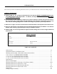
INTRODUCTION This manual provides the following information about your Mounted Harrow or Mounted Rolling Chopper. ITEMS OF IMPORTANCE A. Summers Mfg. Co., Inc. strongly recommends that each Operator READ and UNDERSTAND the Operator’s Manual before using the machine. In addition, this Operator’s Manual should be REVIEWED at least ANNUALLY thereafter. B. It is the policy of this company in improve its products whenever possible and practical to do so.
SECTION 1 - SAFETY SAFETY-ALERT SYMBOL This symbol is used to denote possible danger And care should be taken to prevent bodily Injury. This symbol means: ATTENTION! BECOME ALERT! YOUR SAFETY IS INVOLVED! Definition of each Signal Word used in conjunction with the Safety-Alert symbol. DANGER WARNING CAUTION indicates an imminently hazardous situation which, if not avoided, will result in death or serious injury. This signal word is to be limited to the most extreme situations.
SECTION 1 - SAFETY SAFETY DURING TRANSPORT 1. ONLY TOW at a safe speed. Use caution when making corners or meeting traffic. 2. USE a safety chain between tractor drawbar and implement hitch when transporting on public roads. 3. ALWAYS use transport locks when transporting on public roads. 4. COMPLY with local lighting, marking and maximum width regulations when transporting on highways. SAFETY DECALS 1. KEEP SAFETY DECALS AND REFLECTORS CLEAN. 2. REPLACE missing or unreadable decals.
SECTION 1 - SAFETY 3. WING DANGER DECAL (PN 8Z0344) 4. ELECTROCUTION DANGER DECAL (PN 8Z0346) 5.
SECTION 1 - SAFETY 6. AMBER REFLECTOR (PN 8Z0800) 7. RED-ORANGE REFLECTOR (PN 8Z0805) 8.
SECTION 1 - SAFETY GENERAL ASSEMBLY SAFETY PRACTICES YOU ARE RESPONSIBLE for the safe assembly of the machine. ALWAYS INSPECT LIFTING CHAINS AND SLINGS for damage or wear. DO NOT ALLOW CHILDREN or other unauthorized persons within the assembly area. BE SURE LIFTING DEVICE IS RATED TO HANDLE THE WEIGHT. WEAR PERSONAL PROTECTIVE EQUIPMENT which includes a hard hat, eye protection, work gloves and steel toed boots with slip resistant soles.
DISK MOUNTED HARROW INSTALLATION GUIDE Disk brackets and Spacer Tubes for M94 through M108 Mounted Harrow See Pages 2.05 – 2.07 of Whole Goods Catalog for Sections Required Use one short disk bracket with sections supported by one mounting arm. Use two short disk brackets to mount a single harrow section across disk center. At locations other than disk center, a combination of brackets and spacers (listed below) are required to attach mounted harrows to an angled implement frame.
8W1897 8H1394 8H1327 8H1309 8D5219 8X0269 8H2131A 8H1315 WING-ARM TRAVEL STOP MATCH LOCATION LETTER ON SUPPORT ROD ASSEMBLY 7 8X0117 3/4 X 7" 8X0099 5/8" X 6-3/4" 8X0100 5/8" X 8" (GR8 RLLNG BSKT) 8X0101 5/8" X 8" (GR5 MNTD HRRW) 8X0250 5/8" N 8X0222 1/4" LN 8W1204 1/2 X 3 X 3" 8X0261 3/4" LN 8X0123 3/4" X 5.
8
9
6', 8' & 10' 3 BAR SECTION ASSEMBLY MODEL 104-108 8HD5180 (OPTIONAL) 8H1180S (1/2 X 20") 8H1184S (1/2 X 26") 8H1190S (9/16 X 26") 8H1195S (5/8 X 28") 8X0240 1/2" N 8X0240 1/2" N 8X0303 1/2" LW 8HD5140 - 6' (23-3/8") 8HD5150 - 8' (47-3/8") 8HD5160 - 10' (71-3/8") 8X0063 1/2 X 1-1/2" 8HD5101 (LEFT) 8X0078 1/2" X 3-1/2" 8X0067 1/2-13NCX2-1/4" 8X0066 1/2 X 1-3/4" 8HD5115 8X0242 NY-LOCK 1/2" N 10 8X0242 NY-LOCK 1/2" N 8HD5052 - 6' (61-1/2") 8HD5072 - 8' (85-1/2") 8HD5082 - 10' (109-1/2") 8HD0080 8X0
6, 8' & 10' 4 BAR SECTION ASSEMBLY MODEL 104-108 8HD5140 - 6' (23-3/8") 8HD5150 - 8' (47-3/8") 8HD5160 - 10' (71-3/8") 8HD5180 (OPTIONAL) 8X0063 1/2 X 1-1/2" 8H1180S (1/2 X 20") 8H1184S (1/2 X 26") 8H1190S (9/16 X 26") 8H1195S (5/8 X 28") 8X0240 1/2" N 8X0303 1/2" LW 8X0330 1/2" FW 8HD5105 (LEFT) 8X0067 1/2-13NCX2-1/4" 8X0303 1/2" LW 11 8X0078 1/2" X 3-1/2" 8X0066 1/2 X 1-3/4" 8X0242 NY-LOCK 1/2" N 14 8X0242 NY-LOCK 1/2" N 21 8HD0080 16 8HD0202 8Z0114 M104 DECAL 8Z0115 M105 DECAL 8Z0118 M10
5/8" BOLT LENGTH AS REQUIRED 8X0304 5/8" LW 8H1532 8X0250 5/8" N 8X0304 5/8" LW 8H1510 (6" MAX. FRAME) 8H1512 (11" MAX. OPT.) 8X0093 5/8" X 2" 8X0250 5/8" N 8H1510 (6" MAX.) 8H1512 (11" MAX. OPT.) 8H1530 8H1612 DISK BRCKT LONG W/PLATE - HIGH CLEARANCE 8H1610 DISK BRCKT LONG W/PLATE - UNIVERSAL 12 8H1522 8H1520 8X0304 5/8" LW 8H1510 (6" MAX.
JD 510/512 DISK RIPPER WITH SUMMERS HARROWS WIDTH SECTIONS REQRD CNTR SECT 8H2310 8HD5250 8H1600 8H1505 WING ARM MNTNG PKG DISK BRCKT SPACER, 4” 5 Shank / 12 1/2’ Width 2: 8’ –– 4 1 –– –– 7 Shank / 17 1/2’ Width 2: 10’ –– 4 1 –– –– 9 Shank / 22 1/2’ Width 1: 6’ and 1: 8’ 6’ (EA) 8 4 (WING) 1 2 (WING) 1. Bolt extensions to 510 main frame as shown (flush side down). 2. U-bolt 4X4 to extensions (center on machine). 3. Bolt arms to 4X4 tube. 4. U-bolt sections to arms.
MOUNTING INSTRUCTIONS FOR SUMMERS Mounted Harrows on Cultivators, Chisel Plows and Disk Some tillage implements have close to 180 degrees of wing travel into transport position. Machines like this include short wing machines with low transport height and 5 section machines (outside wings only). This type of fold can cause interference problems with SMC Mounted Harrows. The following are steps to prevent problems: MODEL 74: 1.
15
SECTION 1 BASIC LAYOUT AND ASSEMBLY; MODEL 74 Fig. 3. 3a. Attach side plates to carrier arms using two 1/2 x 3” bolts per arm (use a heavy flat washer on each side). Mount in front, middle or rear set of holes depending on desired clearance between front harrow bar and implement. Place in second hole up from bottom for initial level adjustment. If mounting brackets are spaced at the calculated distance, mount side plates on the same side of lift arms.
Fig. 6. 6a. Install 7/16 x 1-3/4” clevis pin in top hole and back-up clip in adjusting bar as shown. Back-up clip allows implement to be backed up without damage to harrow teeth if they do not clear the ground. Fig. 7. 7a. Lock-up clip shown installed (see arrow) to hold harrow up in a raised position. Fig. 5. 5a. Attach levers to bars be removing the existing bolts and using 1/2 x 3-3/4” bolts supplies. Discard harrow tooth washer. Secure using original locknut.
SECTION 2 SPECIAL BRACKETS FOR JD1610 CHISEL PLOWS MOUNTING INSTRUCTIONS FOR SUMMERS MOUNTED HARROWS ON JOHN DEERE 610 CHISEL PLOW Shown below is the layout of mounted harrows on a 41’ JD610 Chisel Plow (over center fold with 12” shank spacing). Three 14’ sections are used with three model 74 carrier arms per section. Two spacer tubes for lateral positioning are recommended (order Summers PN 8H1502 for one spacer tube). An optional method is to use two 7’ sections in place of one 14’ section.
SECTION 3 DISK MOUNTING BRACKETS PN 8H1600 (13”) PN 8H1610 (25”) PN 8H1602 (20”) PN 8H1612 (29”) Universal Disk Mounting Bracket, Short (w/mounting plate & hardware) Universal Disk Mounting Bracket, Long (w/mounting plate & hardware) High-Clearance Disk Mounting Bracket, Short (w/mounting plate & hardware) High-Clearance Disk Mounting Bracket, Long (w/mounting plate & hardware) All of the above brackets are designed to be used with Summers M74, M94, M104 or M106 mounting arms.
SECTION 4 SPECIAL BRACKETS FOR JD235 DISKS Order mounting package PN 8H1580 for 19-26 ft. models Order mounting package PN 8H1582 for 27-31 ft. models 1a. The photo to the right shows a 30’-1” JD235 disk with a 3 bar M74 Mounted Harrow. See the figures and sizing chart below for harrow layout on all size models. 2. Bracket layout for 19-26’ models. 22’9” model shown in above figure. for two different size disk. The number of harrow teeth between carrier arms are represented by an “X”.
JD235 DISK FRAME MOUNTING BRACKET SELECTION CHART Bracket No. 1 2 3 4 5 6 19-26 Ft. Models Bracket Description Long Hi-Clearance Modified Short Univ. (See Fig. 3a) Modified Short Univ. (See Fig. 4a) Modified Short Univ. (See Fig. 4a) 235 Bracket & Spacer Tube (Fig. 5a) Short Hi-Clearance 27-31 Ft. Models Bracket Description Short Hi-Clearance Long Universal Long Univ. & Extension Tube Long Universal Long Universal Short Hi-Clearance These brackets bolt to a disk frame using existing holes in the frame.
SECTION 5 PACKING LISTS PACKING LIST FOR ALL MODELS For 2 bar attachments, order 3 bar brackets and 2 bar hardware package (PN 8H0200 – One required per pair) PACKING LIST FOR PN 8H1590 Model 74 Model 74 JD1610 Chisel Plow Mounting Package 3 Bar 4 Bar PN 8H1330 8H1332 8H1340 8H1350 8H1362 8H1368 8H1370 8H1375 8H1380 8H1382 8H1385 8H1390 8H1403 8H1404 Description 8H0374 Side Plate, 3 Bar 2 Side Plate, 4 Bar Mounting Plate 2 Mounting Bracket 2 Carrier Arm, M74 2 Lever, 2 Bar Lever, 3 Bar 4 Lever w
8X0244 1/2" FLG TOP LOCK NUT 23' & 30' NARROW CENTER ONLY 8C9030 (4') 8C9035 (5') 8C9040 (7') FRAME 8J4290 8D0340 8C9010 8C0150 8X0256 5/8" FLNG NUT 8X0266 3/4" FN 8C9050 (4') 8C9055 (5') 8C9060 (7') REEL ONLY 8S0358 5/8 x 3 x 4-1/2" 8X0256 5/8" FLNG NUT 23 8X0064 CRG 1/2 X 1-1/2" 8S0358 5/8 x 3 x 4-1/2" 8X0246 1/2" FN BLADE 3/8X3 - 16-3/8" ASSEMBLY WIDTH QTY 4' 12 5' 16 7' 20 8C9017 8X0725 1/8" ZERK 8X0250 5/8" N 8X0304 5/8" LW REAR STABILIZER 8D8523 DROP LEG JACK 8X0101 5/8" X 8" 8H2102 (
NOTES 24