WINE CELLARS Model Nos.: SWC007/ALWC15/SWC1535B/SWC1102/SWC1875B/ SWC1926/SWC1966 Instruction Manual BEFORE USE, PLEASE READ AND FOLLOW ALL SAFETY RULES AND OPERATING INSTRUCTIONS. Write Model & Serial Numbers (on lower left corner of inside cabinet) here: Model No. _______________________________________ Serial No. _______________________________________ Felix Storch, Inc. ISO 9001:2015 registered 770 Garrison Avenue Bronx, NY 10474 www.summitappliance.
APPLIANCE SAFETY Your safety and the safety of others are very important. We have provided many important safety messages in this manual and on your appliance. Always read and obey all safety messages. This is the Safety Alert Symbol. The symbol alerts you to potential hazards that can kill or injure you and others. All safety messages will follow the Safety Alert Symbol and either the words DANGER or WARNING.
- Avoid open flames and anything that creates a spark, - Disconnect from the electrical power line, - Air the room in which the appliance is located for several minutes, and - Contact the Service Department for advice. The more coolant there is in an appliance, the larger the room it should be installed in. In the event of a leakage, if the appliance is in a small room, there is the danger of combustible gases building up. For every ounce of coolant, at least 325 cubic feet of room space is required.
LOCATION OF PARTS MODEL SWC007 Door Digital Control Panel Handle Ventilation Grille Adjustable Legs Cabinet MODEL ALWC15 Digital Control Panel Door Shelves(5) Handle Security Lock Ventilation Grille Adjustable Legs Cabinet 4
MODEL SWC1535B Digital Control Panel Door Shelves(6) Handle Security Lock Ventilation Grille Adjustable Legs Cabinet MODEL SWC1875B Digital Control Panel Upper Door Handle Upper Zone Security Lock Lower Door Lower Zone Shelves (14) Ventilation Grille Adjustable Legs Cabinet 5
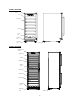
MODEL SWC1102 Digital Control Panel Handle Shelves (12) Door Security Lock Ventilation Grille Adjustable Legs Cabinet MODEL SWC1926 Digital Control Panel Door Handle Shelves (15) Security Lock Ventilation Grille Adjustable Legs 6
MODEL SWC1966 Door Digital Control Panel Handle Shelves (14) Security Lock Ventilation Grille Adjustable Legs Cabinet INSTALLATION INSTRUCTIONS BEFORE USING YOUR APPLIANCE Remove the exterior and interior packing. Before connecting the appliance to the power source, let it stand upright for approximately 2 hours. This will reduce the possibility of a malfunction in the cooling system from handling during transportation. Clean the interior surface with lukewarm water using a soft cloth.
the top are suggested, which allows the proper air circulation to cool the compressor and condenser for energy saving. Even for built-in installation, it is a must to keep at least 1/8” (3mm) of space on each side, 5/8” (16mm) at the back and 1/16” (1.6mm) at the top to ensure proper service access and ventilation. And the air vent at the front of the appliance must never be covered or blocked in any way.
When moving the appliance, be careful not to damage the power cord. EXTENSION CORD Because of potential safety hazards under certain conditions, it is strongly recommended that you do not use an extension cord with this appliance. However, if you must use an extension cord it is absolutely necessary that it be a UL/CUL-Listed, 3-wire grounding type appliance extension cord having a grounding type plug and outlet and that the electrical rating of the cord be 115 volts and at least 10 amperes.
- Model SWC1875B 9 4 3 1 5 2 6 2 1 10 7 8 3 11 4 5 1. Remove the right bottom hinge (1) by unscrewing the four screws (2). Be careful to hold the lower glass door (3) firmly after removing the screws. And then gently pull down to remove the lower glass door from the middle hinge and place it on a padded surface to avoid the risk of damage. (Fig. 1) 2. Unscrew and transfer the door adapter (7) and (10) to the designated opposite position of lower glass door.
9. Set the lower glass door to the designated position. Then screw the left bottom hinge on the left designated position and tighten them 10.Recheck and adjust the lower door alignment by loosening the screws (8) &(9) and moving the door adapter (7) & (10). Tighten the screws (8) & (9) after the door is leveled. 11. Transfer the handles and plugs to the opposite positions.(See page 12, Handle Installation) - Models SWC1102/SWC1926/SWC1966 4 1 2 6 5 7 3 2 1 8 3 9 1 4 3 2 5 1.
ADJUSTING THE HEIGHT OF THE UNIT for MODELS SWC007 & ALWC15 The height of the unit can be increased by up to 3” by turning the adjustable legs. Once the desired height has been achieved, the gap between the kick-plate and the floor can be covered by using a kick-plate extender, which is described in the next section. ADJUSTING THE KICK-PLATE for MODELS SWC007 & ALWC15 This appliance includes an adjustable kick-plate extender that is not required to operate the unit.
RECOMMENDED TEMPERATURE SETTINGS Conservation Red Wines Dry/White Wines Rosé Wines Sparkling Wines 49 ~ 57ºF 58 ~ 72ºF 48 ~ 57ºF 49 ~ 51ºF 41 ~ 47ºF 10 ~ 14ºC 15 ~ 22ºC 9 ~ 14ºC 10 ~ 11ºC 5 ~ 8ºC CONTROL PANEL for SWC007 CONTROL PANEL for ALWC15 / SWC1535B/SWC1102/SWC1926 ON/OFF Power To turn the appliance off, press and hold the key for 5 seconds until temperature display goes out. To turn the appliance on, press and hold the key for 1 second until temperature display lights up.
(The temperature preset at the factory is 54°F or 12°C.) The temperature you are setting will increase by one degree each time you touch the Up symbol, and will decrease by one degree each time you touch the DOWN symbol. The range of the temperature control is from 41°F to 72°F. To view the set temperature at any time, touch the UP or DOWN symbol. The set temperature will flash in the display window for 5 seconds. After 5 seconds, the temperature inside the unit will reappear in the display window.
When the unit is plugged in for the first time, the unit will power up automatically to the preset defaults. The preset temperature at the factory for the UPPER temperature zone is 50ºF (10ºC) and for the LOWER temperature zone is 60ºF (16ºC). You can press the left side UP and DOWN keys to control the internal temperature of the UPPER temperature zone and press the right side UP and DOWN keys to control the internal temperature of the LOWER temperature zone.
TEMPERATURE MEMORY FUNCTION In the event of a power interruption (power surge, breaker switch, etc.), the unit will remember the previous temperature settings, and when the power is recovered, the cabinet temperature will return to the same setting as before the power went off. TEMPERATURE ALARM / DOOR ALARM The audible alarm sounds if the storage temperature is not cold enough. The temperature display flashes at the same time.
STORAGE Bottles can differ in size. Accordingly, the actual number of bottles you can store may vary. The approximate maximum bottle capacity can be achieved when storing traditional 750 ml Bordeaux bottles in bulk storage. You may load your wine bottles in single rows or by stacking while taking note of the following: if you do not have enough bottles to fill your wine cellar, it is better to distribute the load throughout the wine cellar so as to avoid “all on top” or “all below” type loads.
CARE AND MAINTENANCE CLEANING YOUR WINE CELLAR Turn off the power, unplug the appliance, and remove all items, including shelves. Wash the inside surfaces with a solution of warm water and baking soda (about 2 tablespoons of baking soda to a quart of water). Wash the shelves with a mild detergent solution. Wring excess water out of the sponge or cloth when cleaning the area where the controls are located, or any electrical parts.
TROUBLESHOOTING You can solve many common problems easily, saving you the cost of a possible service call. Try the suggestions below to see if you can solve the problem before calling the servicer. Troubleshooting Guide PROBLEM Appliance does not operate. POSSIBLE CAUSE Appliance is not connected to a power supply. The appliance is turned off. Tripped circuit breaker or a blown fuse. The temperature is not set correctly. The ambient temperature could require a lower temperature setting.
The appliance is not properly level. The door will not close properly. Display “E0”, “E1”. “E2”, “E3”, “E4”, “E5” or “E7”. The alarm sounds and the temperature display flashes. The icon “--” is lit up and flashing in the temperature display. The door was reversed and not properly re-installed. The gasket is dirty. The shelves are out of position. “E0” indicates a communication error for 3-zone models. “E1” or “E2” indicates that the air temperature sensor has failed.
NOTES 21
NOTES 22
NOTES 23
LIMITED WARRANTY ONE-YEAR LIMITED WARRANTY Within the 48 contiguous United States, for one year from the date of purchase, when this appliance is operated and maintained according to instructions attached to or furnished with the product, warrantor will pay for factory-specified parts and repair labor to correct defects in materials or workmanship. Service must be provided by a designated service company. Outside the 48 states, all parts are warranted for one year from manufacturing defects.