WINE CELLARS Model Nos.: SWC1535B/SWC1102/SWC1875B/SWC1926/SWC1966 Instruction Manual BEFORE USE, PLEASE READ AND FOLLOW ALL SAFETY RULES AND OPERATING INSTRUCTIONS. Write Serial No. (on lower left corner of inside cabinet) here: ___________________________________________ Felix Storch, Inc. 770 Garrison Avenue Bronx, NY10474 www.summitappliance.
TABLE OF CONTENTS Appliance Safety 3 Important Safeguards 3-4 Location of Parts 5-7 Installation Instructions 7-12 Before Using Your Appliance 7 Installation of Your Appliance 7-8 Built-in Cabinet Instructions 8 Electrical Connection 8 Extension Cord 9 Reversing the Door Swing of Your Appliance Installing the Stainless Steel Handle 9-11 12 Operating Your Appliance 12-16 Recommended Temperature Settings 12 Control Panel for SWC1535B/SWC1102/SWC1926 12-13 Control Panel for SWC1875B/S
APPLIANCE SAFETY Your safety and the safety of others are very important. We have provided many important safety messages in this manual and on your appliance. Always read and obey all safety messages. This is the Safety Alert Symbol. The symbol alerts you to potential hazards that can kill or injure you and others. All safety messages will follow the Safety Alert Symbol and either the words DANGER or WARNING.
- Avoid open flames and anything that creates a spark, - Disconnect from the electrical power line, - Air the room in which the appliance is located for several minutes, and - Contact the Service Department for advice. • The more coolant there is in an appliance, the larger the room it should be installed in. In the event of a leakage, if the appliance is in a small room, there is the danger of combustible gases building up. For every ounce of coolant at least 325 cubic feet of room space is required.
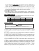
LOCATION OF PARTS MODEL SWC1535B Digital Control Panel Door Shelves(6) Handle Security Lock Ventilation Grille Adjustable Legs Cabinet MODEL SWC1875B Digital Control Panel Upper Door Handle Upper Zone Security Lock Lower Door Lower Zone Shelves (14) Ventilation Grille Adjustable Legs Cabinet 5
MODEL SWC1102 Digital Control Panel Handle Shelves (12) Door Security Lock Ventilation Grille Adjustable Legs Cabinet MODEL SWC1926 Digital Control Panel Door Handle Shelves (15) Security Lock Ventilation Grille Adjustable Legs Cabinet 6
MODEL SWC1966 Door Digital Control Panel Handle Shelves (14) Security Lock Ventilation Grille Adjustable Legs Cabinet INSTALLATION INSTRUCTIONS BEFORE USING YOUR APPLIANCE • Remove the exterior and interior packing. • Before connecting the appliance to the power source, let it stand upright for approximately 2 hours. This will reduce the possibility of a malfunction in the cooling system from handling during transportation. • Clean the interior surface with lukewarm water using a soft cloth.
for energy saving. Even for built-in installation, it is a must to keep at least 3/16” (5mm) of space on each side, 2” (50mm) at the back and 1/16” (1.6mm) at the top to ensure proper service access and ventilation. And the air vent at the front of the appliance must never be covered or blocked in any way. • NOTE: It is recommended that you do not install the appliance near an oven, radiator or other heating source.
EXTENSION CORD Because of potential safety hazards under certain conditions, it is strongly recommended that you do not use an extension cord with this appliance. However, if you must use an extension cord it is absolutely necessary that it be a UL/CUL-Listed, 3-wire grounding type appliance extension cord having a grounding type plug and outlet and that the electrical rating of the cord be 115 volts and at least 10 amperes.
- Model SWC1875B 3 4 1 2 5 6 1 7 8 9 10 5 1. Remove the bottom hinge 1 by unscrewing the four lock screws 2. Be careful to hold the lower glass door firmly after removing the screws. Then gently pull down to remove the lower glass door from the middle hinge 8 and place it on a padded surface to avoid the risk of damage. (Fig. 1) 2. Unscrew and transfer the lower door adapters 4 & 5 to the left designated positions of glass door. (Fig. 2) 3.
9. Remove the handles from the left side of the doors and install them on the right side. (See page 12.) Model SWC1102/SWC1926/SWC1966 5 3 1 2 4 6 1 3 8 1. Remove the bottom hinge 1 by unscrewing the four lock screws 2. Be careful to hold the glass door firmly after removing the screws. (Fig. 1) 2. Gently pull down to remove the glass door from the right top hinge and place it on a padded surface to avoid the risk of damage. Then remove the right top hinge 7. (Fig. 4) 3.
INSTALLING THE STAINLESS STEEL HANDLE This appliance includes a stainless steel handle that is not required to operate the unit. To install the handle, follow the instructions below: Locate the handle 1 over the pins 3 of the door and tighten the handle by screwing in screws 2 with an Allen wrench.
Indicator Light The indicator light is located at the right lower corner of the display. The indicator light will be on when a multi-key function is selected. To perform a multi-key function, press and hold the first key, then press the second key for at least 5 seconds and then release both keys. ºF/ºC Selector Select the temperature display setting in Fahrenheit or Celsius degree.
from Fahrenheit to Celsius or from Celsius to Fahrenheit, press and hold the LIGHT key for 5 seconds. Setting the Temperature Control • The unit has two separate temperature zones. The temperature of both zones can be set between 41ºF and 72ºF (5ºC and 22ºC). The LOWER temperature zone is ideal for storing red and white wines at a setting of 55°F to 72°F (13°C to 22°C). The UPPER temperature zone is suitable for storing champagne and white wines at a setting of 41°F to 55°F (5°C to 13°C).
To initiate Sabbath mode, press the POWER and LIGHT keys at the same time for at least 5 seconds. The indicator light will flash four times and confirm the Sabbath mode is ON. Sabbath mode can be exited by repeating the above process. The Sabbath Mode will automatically turn off after 96 hours. TEMPERATURE MEMORY FUNCTION In the event of a power interruption (power surge, breaker switch, etc.
drainage channel behind the rear wall of the unit, and flows through the drainage hole into the drip tray by the compressor where it evaporates. • However, frost may accumulate on the evaporator if the unit is repeatedly opened in a high heat or high humidity location. If this frost pattern does not clear within 24 hours, your unit will require manual defrosting. STORAGE Bottles can differ in size. Accordingly, the actual number of bottles you can store may vary.
CARE AND MAINTENANCE CLEANING YOUR WINE CELLAR • • • • • • Turn off the power, unplug the appliance, and remove all items, including shelves. Wash the inside surfaces with a solution of warm water and baking soda (about 2 tablespoons of baking soda to a quart of water). Wash the shelves with a mild detergent solution. Wring excess water out of the sponge or cloth when cleaning the area where the controls are located, or any electrical parts.
TROUBLESHOOTING You can solve many common problems easily, saving you the cost of a possible service call. Try the suggestions below to see if you can solve the problem before calling the servicer. Troubleshooting Guide PROBLEM Appliance does not operate. POSSIBLE CAUSE • Appliance is not connected to a power supply. • The appliance is turned off. • Tripped circuit breaker or a blown fuse. • The temperature is not set correctly. • The ambient temperature could require a lower temperature setting.
• The appliance is not properly level. The door will not close properly. Display “E0”, “E1”. “E2”, “E3”, “E4”, “E5” or “E7”. The alarm sounds and the temperature display flashes. The icon “--” is lit up and flashing in the temperature display. • The door was reversed and not properly installed. • The gasket is dirty. • The shelves are out of position. • “E0” indicates a communication error for 3-zone models. • “E1” or “E2” indicates that the air temperature sensor has failed.
LIMITED WARRANTY ONE-YEAR LIMITED WARRANTY Within the 48 contiguous United States, for one year from the date of purchase, when this appliance is operated and maintained according to instructions attached to or furnished with the product, warrantor will pay for factory-specified parts and repair labor to correct defects in materials or workmanship. Service must be provided by a designated service company. Outside the 48 states, all parts are warranted for one year from manufacturing defects.