USER’S MANUAL Marvel Series HP-1 HP-1L HP-1S
TABLE OF CONTENTS Introduction 1 Components 2 Safety Instructions 3 Environmental Conditions 6 Assembly & Disassembly 7 Adjustments for Seating Comfort 11 Operation 12 Batteries and Charger 16 Maintenance and Repair 18 Specifications 21 Limited Warranty 22
INTRODUCTION Thank you for choosing a Summit Power mobility product. We hope that it will provide many years of mobility for you. This is a general manual for our power wheelchairs, HP-1, HP-1L, and HP-1S. The information in this manual applies to all these models. HP-1 is a power wheelchair with seat width of 18”, HP-1L with 20” seat width and HP-1S with 16” seat width. We use “HP-1” or “power wheelchair ” to refer to all these models in this manual.
COMPONENTS Your power wheelchair is shipped partially disassembled to protect it during shipping. After unpacking, please check whether you have received the following main components as our standard specification (Fig. 1). 1. 2. 3. 4. 5. 6. 7. Main frame with motor and gearbox Flip-back arm sub-assembly Controller Controller supporting bar Charger Cushion Battery boxes 8. Battery supporting bar 9. Battery knobs 10. Anti-tippers 11. Footrest strap 12. Footrest 13.
SAFETY INSTRUCTIONS Operation of Chair 1. Always ensure that the power is switched off when getting in or out of the wheelchair. This will eliminate the possibility of accidentally activating the joystick and causing injury to yourself or others. 2. Always check that the drive wheels are engaged (drive mode) before driving. 3. Set the speed control knob according to your driving ability and the environment in which you are going to operate.
SAFETY INSTRUCTIONS B Position chair so that the distance between your power chair and the object to which you are transferring is close enough for a safe transfer. B Turn the power off. B Ensure that your power chair is not in freewheel mode. B Flip up or remove armrests. B Flip up footplate or remove footrest or legrest. B Turn both caster wheels towards the transfer direction to improve power chair stability during transfer. 12.
SAFETY INSTRUCTIONS Electromagnetic Interference (EMI) from Radio Wave Sources The rapid development of electronics, especially in the area of communications, has saturated our environment with electromagnetic (EM) radio waves that are emitted by television, radio and communication signals. These EM waves are invisible and their strength increases as one approaches the source.
SAFETY INSTRUCTIONS TURN OFF YOUR POWERED WHEELCHAIR AS SOON AS POSSIBLE WHEN EXPERIENCING THE FOLLOWING: ! ! ! Unintentional motions. Unintended or uncontrollable direction. Unexpected brake release. The FDA has written to the manufacturers of power wheelchairs asking them to test new products to be sure they provide a reasonable degree of immunity against EMI.
ASSEMBLY & DISASSEMBLY ASSEMBLY A. Opening the wheelchair Standing at one side of the wheelchair, tilt it to one side, and push down firmly on the seat rails. The seat should be locked into the receivers on the wheelchair side frame when the chair is fully opened. B. Installing the batteries (not provided) + Note: We recommend using a battery with 12 volt 34AH (for example, U-1) for better performance. Each battery weighs more than 23 lbs. as an average.
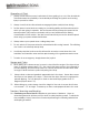
ASSEMBLY & DISASSEMBLY C. Installing the controller Controller Supporting Bar Your power wheelchair comes standard with a swing-away joystick controller. To install the controller, simply fasten it to the controller supporting bar with the two (2) black screws provided (Fig. 6). Fig. 6 D. Connecting the main cables Plug the three main cables (connected to left, right motor and battery) underneath the seat near the crossbar to the connectors on the other end of the controller.
ASSEMBLY & DISASSEMBLY DISASSEMBLY A. Battery removal For transportation B B B B B Unplug the battery connector from the controller connector underneath the seat near the crossbar. Refer to Assembly, Section D, Connecting the main cables on Page 8. Unscrew the knobs and remove the battery bar at the rear batter y box. Unplug the battery connector that joins the two batter y boxes together. Slide out the battery boxes, one at a time. Lift the battery boxes using the batter y strap.
ASSEMBLY & DISASSEMBLY B. Folding the wheelchair To fold the wheelchair, it is necessary to remove certain components. Follow the simple guidelines below: B B B B B B Turn the wheelchair off. Park the chair on a level surface. Ensure the wheels are in drive (engaged) mode, with controller lever on the vertical position (Fig. 9). Fold up the footrests and remove the entire footrests assembly. Remove the battery boxes. You can refer to Disassembly, Section A, Battery Removal, For Transportation on page 9.
ADJUSTMENTS FOR SEATING COMFORT To maximize seating comfort, your power wheelchair lets you adjust: B B B B Armrest height. Controller position. Flip-back and detachable armrest. Footrest height. A. Armrest height (Adjustable up to 4” in 1” increments) Lever To adjust the armrest height, pull and hold the button on the arm sub-assembly, lift the armrest up to the desired height (Fig. 11). Release the button when the armrest is locked. Button Fig. 11 B.
OPERATION The power wheelchair is simple to operate. However, we recommend that you read carefully the following instructions to become familiarized with your new vehicle. A Word of Caution: Before you turn the power on, always be aware of the environment that surrounds you to select your desired speed. For indoor environments we recommend that you select the slowest speed setting. For outdoor operation of this vehicle we recommend that you select a speed that is comfortable for you to control it safely.
OPERATION B. Controller Display: The controller display is a multifunction visual display. It can provide three types of information: i) ON/OFF status, ii) battery condition meter and iii) fault diagnostics. 1. ON/OFF Status When the power is on, the controller's LED will be lit up. If the LED is not lit, the controller is OFF. 2. Battery Condition Meter The battery condition meter is composed of 6 segments (two each of red, orange, and green). It enables you to monitor battery charge.
OPERATION Note: B You must turn the controller OFF and then ON again to reset the controller, even if the source of the fault is removed/corrected. B If more than one fault exists, then the fault having the highest priority is indicated. C. Free-Wheeling: Because the motors are designed to engage the electromagnetic brakes when the vehicle is not in use or when the power is OFF, they also have a manual feature that allows them to "free-wheel".
OPERATION E. Thermal Protection: Your power wheelchair controller is equipped with a safety system called thermal rollback. A built-in circuit monitors the temperature of the controller and motors. In case of excessive heating of the controller and motors, the controller reduces the motor voltage and speed of the power wheelchair. The reduction of the speed allows the electrical components to cool down.
BATTERIES & CHARGER BATTERY We recommend that you use deep-cycle batteries that are sealed and maintenance free for your power wheelchair. Both sealed lead-acid (SLA) and gel cell are deep-cycle batteries and are similar in performance. Deep-cycle batteries are specifically designed to provide power, drain down, and then accept a relatively quick recharge. Lead-acid batteries should be charged as often as possible.
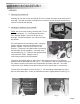
BATTERIES & CHARGER CHARGING INSTRUCTIONS To recharge the batteries, follow the steps below: B Place your power wheelchair close to a standard electrical wall outlet. Charging socket B Turn the controller power OFF. B Connect the charger connector to the control box charging socket (Fig. 17). B Plug the charger power cord into a standard wall outlet. B Turn the charger switch ON. A red and a yellow (if battery Fig. 17 charge is low) LED will illuminate.
MAINTENANCE & REPAIR Your power wheelchair is designed for minimal maintenance. However, like any motorized vehicle it requires routine maintenance. To keep your HP-1 for years of troublefree operation, we recommend you follow the following maintenance checks as scheduled. DAILY CHECKS 1. With the controller turned OFF, perform a joystick check. Make sure it is not bent or damaged and that it returns to center when you release it. Visually inspect the rubber boot around the base of the joystick for damage.
MAINTENANCE & REPAIR SEMI-ANNUAL CHECKS 1. Z Check the motor brushes. We recommend that your authorized dealer inspect the brushes every six months, or sooner if your power wheelchair is not operating smoothly. If inspection determines excessive wear on the brushes, they must be replaced or motor damage will result. Warning! Failure to maintain the brushes could void the power wheelchair’s warranty. To inspect or replace the motor brushes: 1. 2. 3. 4. 2. Motor Brush Caps Fig.
MAINTENANCE & REPAIR Note: If you experience any technical problems, it is recommended that you check with your local dealer before attempting to troubleshoot on your own. The following symptoms could indicate a serious problem with your power wheelchair. Contact your local dealer if any of the following arises: 1. 2. 3. 4. 5. 6. 7. 8. 9.
SPECIFICATIONS HP1 HP1L HP1S 43.5 43.5 43.5 MAXIMUM SPEED DIMENSION Width close: 17.5 20.0 14.5 RANGE (INCHES) Width open: 25.5 27.5 23.5 TURNING RADIUS Height: 38.0 38.0 38.0 GRADIENT Width: 18.0 20.0 16.0 GROUND CLEARANCE SEAT Depth: 16.0 16.0 16.0 (INCHES) Height: 20.5 20.5 20.5 DRIVE TRAIN Back height: 17.0 17.0 17.0 MOTOR Length: FRONT CASTERS 8” x 2” Solid REAR WHEELS 12” x 2.5” Solid (Option: Pneumatic) WEIGHT CAPACITY (LBS.
LIMITED WARRANTY Five-Year Limited Warranty: Power chair frame We will repair the frame with new or refurbished parts, free of charge, in the USA, in the event of defective materials or workmanship. One-Year Limited Warranty: Electronic controller, drive train components We will repair these products with new or refurbished parts, free of charge, in the USA, for one-year from the original date of purchase in the event of defective materials or workmanship.
authorized SUMMIT DME dealer