Service Manual Tumble Dryer - TD70.
Service Manual Contents Tumble Dryer TD70.C Updates...................................................................................................................................................................................................................................................4 Introduction..........................................................................................................................................................................................................
Service Manual TD70.C Updates Rev Date Description Initials 01 2011-09-06 First version FH 02 2011-11-16 New document structure ISC 03 2012-01-20 New revision circuit diagram EH 04 20123-05-02 Updated the service menu BPA 05 2012-05-03 Changed the infromation about Autofilter BPA 06 2012-05-04 Updated part no control units, irrelevant articles deleted. EH 07 2012-07-05 Troubleshooting TD70 HP, LCD F29, removing back rear included.
Service Manual TD70.C Introduction You are holding the Service manual for the TD70 tumble dryer. The TD70 tumble dryers is available in several models, designated TD70.1, TD70.2, TD70.3. The TD70.C model, that this guide is focusing on, is designed for professional use. It should be easy to service a tumble dryer. It is important that you, as a service technician, are provided the necessary conditions to work in an efficient and satisfactory manner.
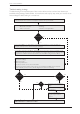
Service Manual TD70.C Troubleshooting strategy Troubleshooting is an important part of the service callout, and as such we have drawn up a troubleshooting strategy that describes, in broad terms and step by step, what you need to do to find and diagnose faults arising in our machines. • Ask the customer to describe the problem. • Check whether the customer’s description matches the reported fault.
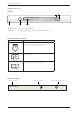
Service Manual TD70.C Product overview TD70.C S2 S1 J1 S3 DISPLAY Programmes: A total of 7 programmes. Settings: 4 settings (Language, Child-safe, Buzzer, Heater 2) Knob and button descriptions Description Turn/Push Programme selector (J1) Turn clockwise or anti-clockwise to cycle through the different programmes and options in the various menus. Start button (S2) • Starta programme T 7 5 3 C B U T T E R FStop L Y D R (S3) Y I N G button • Stop programme (press and hold for 3 seconds).
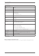
Service Manual TD70.C Technical data Technical information Height 850 mm Width 595 mm Depth 585 mm Weight 43 kg (Vented) 47 kg (Condenser) 55 kg (Heat pump) 44 kg (Heating Water Circuit) Cylinder volume 112 litres Capacity EU 7.0 kg US/AU 7.
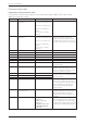
Service Manual TD70.C Component description Components and measurement values The specified resistance values apply at room temperature (about 20°C/68°F). Values within ±10% are considered normal. Article no. 80 839 15 Component Motor 50 Hz, 220/240 V 80 839 16 Motor 60 Hz, 220/240 V 80 903 13 80 903 14 80 902 70 80 902 71 80 821 28 80 846 48 80 762 02 Capacitor Capacitor Capacitor heat pump Capacitor heat pump Condensate pump Condensate pump EMC-filter with inductor 80 833 44 Thermistor 4.
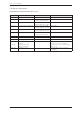
Service Manual TD70.C Component description Components and measurement values cont. Article no. 80 824 92 80 915 90 80 824 91 80 824 60 80 824 61 80 916 18 80 821 22 80 821 23 80 88 415 88 015 22 88 015 02 80 846 49 10 Component Heating element 1950 W Heating element 2500 W Measurement value Comment Heater 1: 1950 W, 24.5 Ω Heater 1: 1950 W, 24.5 Ω Heater 2: 550 W, 91.4 Ω Heating element 3000 W Heater 1: 1950 W, 24.5 Ω Heater 2: 1050 W, 45.5 Ω Heating element 3000 W Heater 1: 1950 W, 90.
Service Manual TD70.C Component description Components and function description Here we describe the function and specification of the most important components. Certain components are found only in more highly specified machines or in particular markets. See the Troubleshooting chapter for fault and information codes. CU (Control Unit) The CU (Control Unit) functions as both a control panel and a logic component.
Service Manual TD70.C Component description Tolerance: ±1% Reset Thermostat Overheating cut-out Co ver pla te ( 65 8x 48 3m m) Thermostat and overheating cut-out The thermostat is installed next to the heating element and is used to reduce the element output by turning it off if the ambient temperature exceeds 135°C (±5°C) for condenser dryers and 110°C (±5°C) for others.
Service Manual TD70.C Component description Door switch The door switch is located in a holder in the middle of the front support and is activated by a pin in the front door. The switch is normally open and closes when the door is closed. If the front door is opened during operation the CU stops the drying programme. The programme starts from the beginning if restarted. Purpose: To prevent the machine from running while the door is open.
Service Manual TD70.C Component description Heating element The heating element is located in the rear section and consists of two separate heating coils. Each heating coil is made from resistance wire. Purpose: To heat the drying air to the right temperature. 2 Heat pump (HP) Certain types of machine are fitted with heat pump systems. These systems are closed circuits that are replaced by replacing the machine’s base plate with a new module. The function settings are adjusted in the service menu.
Service Manual TD70.
Service Manual TD70.C Control unit Circuit diagram TD70.
Service Manual TD70.C RESISTANCES AT ROOM TEMPERATURE (CA. 20°C/68°F) VALUES WITH +/-10% ARE REGARDED AS NORMAL COMPONENT NS R IN PUMP, FLOAT SWITCH CH TIONS INTERFACE EMENT F: RADIO INTERFERENCE SUPPRESSION FILTER 680K Ohm NTC 1: THERMISTOR 1 4 - 6 K Ohm NTC 2: THERMISTOR 2: 4 - 6 K Ohm AP: DRAIN PUMP: 111 Ohm EL: HEATING ELEMENT 1050W 45.3 Ohm EL: HEATING ELEMENT 1950W 20.
Service Manual TD70.C Control unit Circuit diagram TD70.
Service Manual TD70.C RESISTANCES AT ROOM TEMPERATURE (CA.
Service Manual TD70.C Control unit Circuit diagram TD70.
Service Manual TD70.C RESISTANCES AT ROOM TEMPERATURE (CA. 20°C/68°F) VALUES WITH +/-10% ARE REGARDED AS NORMAL COMPONENT NS R AIN PUMP, FLOAT SWITCH CH TIONS INTERFACE EMENT F: RADIO INTERFERENCE SUPPRESSION FILTER 680K Ohm NTC 1: THERMISTOR 1 4 - 6 K Ohm NTC 2: THERMISTOR 2: 4 - 6 K Ohm AP: DRAIN PUMP: 111 Ohm EL: HEATING ELEMENT 1050W 45.3 Ohm EL: HEATING ELEMENT 1950W 20.
Service Manual TD70.C Control unit Circuit diagram TD70.
Service Manual TD70.C RESISTANCES AT ROOM TEMPERATURE (CA.
Service Manual TD70.C Control unit Circuit diagram TD70.
Service Manual TD70.C RESISTANCES AT ROOM TEMPERATURE (CA.
Service Manual TD70.C Troubleshooting Fault indicators In the case of a fault the following fault indicators are shown on the display. S2 S1 J1 S3 DISPLAY Display Cause Action Over flow fault, Overflow Fault, Over flow fault, Överfyllnad, Overløbsfejl, Overflom, Ylitulviminen, Trop plein, Überlauf, Troppo pieno, Desborde, Пeрeлив вoды, Te veel water The microswitch is opened when a full condensed water tank is detected. Detection begins 30 seconds after the programme starts.
Service Manual TD70.C Troubleshooting Fault indicators cont. Display Cause Action Thermistor fault, Thermistor Fault, Thermistor fault, Termistorfel, Termostat fejl, Termistor, Termistorivika, Défaut , Termistorfehler, Termistore , Fallo , Teрмистoр, Temp. sensor fout 1. Thermistor circuit open 2. Thermistor malfunction Service action: Check the thermistor. Replace if necessary. Clean condenser, Rengör kondensor, Rens kon. sator, Rens kon.
Service Manual TD70.C Troubleshooting Other faults If the tumble dryer does not work, you should first check whether this is due to a simple fault, something that the customer can rectify. Fault symptom Cause Action The machine will not start. The outer door is not properly closed. • Check that the door pin is activating the door switch. The machine is not supplied with power. • Check the fuses and connections. The machine stops. The washing does not get dry. Drying is uneven.
Service Manual TD70.C Troubleshooting Other faults cont. Cause Action The machine is leaking water. Improper installed auto filter and/or sealing Information to customer: • Check that the auto filter and the sealing is proper installed. Defective auto filter and/or sealing Information to customer: • Handle the auto Filter and sealing carefully when cleaning. Service action: • Replace the auto filter and/or the sealing.
Service Manual TD70.C Service menu S2 S1 J1 Opening the service menu + T 7 5 3 C B U T T E R F L Y x5 D R Y I N G B U T T E R F L Y D R Y I N G T 7 5 3 C B U T T E R F L Y D R Y I N G T 7 5 3 C B U T T E R F L Y Turn/ Push Check that the machine is switched off. Otherwise switch off the main power by pressing the main power switch (S1). Press and hold the Start button (S2) while turning on the main power with the main power switch (S1).
Service Manual TD70.C Service menu cont. S1 J1 Turn/ Push DISPLAY Display Comments/instructions Test No component tested Test motor The motor runs at normal speed Test heater 1 The motor runs at normal speed. Heating element 1 is switched on and off by the CU depending on the values registered by thermistors 1 and 2. Max. temp. 70°C. (Only if setting for heat pump is Heat Pump Off ) Test heater 2 The motor runs at normal speed.
Service Manual TD70.C Service menu cont.
Service Manual TD70.C Service menu cont.
Service Manual TD70.C Service and installation Dismount top cover and back rear Instructions 1. Unscrew the top cover. 2. Dismount the panel rear cover by removing the screws and carefully bend in the upper edge. 3. Dismount the heating element by removing the screws and disconnect the cables. 4. Release the nut bearing lock (socket wrench 19). 5. Remove the external fan wheel (socket wrench 10) and unscrew the encircling screws (Torx 10).
Service Manual TD70.C Service and installation Dismount top cover and back rear cont. Instructions Illustration 6. Disconnect the rubber hose. 7. Remove the screws on the rear panel (Torx 20). Note! Make sure that the cylinder not fall down.
Service Manual TD70.C Service and installation Replacing the panel and the control unit Instructions 1. Attach the anti-static wristband to a part of the machine that is earthed! NOTE! An anti-static wristband must be used, otherwise you risk destroying the control card. 2. Unscrew the top cover. 3. Carefully press the catches that secure the panel to the front support. Release the catches from the front support by working the panel outwards. 4.
Service Manual TD70.C Service and installation Replacing the panel and the control unit Instructions Illustration 6. Carefully pull the programme selector from the panel. 7. Use a screwdriver to free the control card from the panel. NOTE! The control card must be placed in an ESD-safe bag. 8. Check that the push button, lens and decorative inlay are in place. Now carefully press the new control card into place. 9.
Service Manual TD70.C Service and installation Transporting a tumble dryer with a heat pump Machines with a heat pump must only be transported upright or placed on the left side when viewed from the front. In extreme cases, laying the machine on any other side, or transporting it in an incorrect manner, may result in making the machine unusable. Let the machine stand for 24 hours after transport before use, otherwise the heat pump may be damaged.
Service Manual TD70.
80 925 40 Rev08 2012-09-17 We reserve the right to make changes. www.asko.