
ElectricRangesUseCare

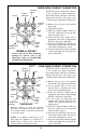


NOTE: The power cord bracket will have
to be reversed for conduit installations.
Detach the bracket and flip its orientation.
Reattach the bracket to the range so the
conduit will pass through the smaller hole.
1. Remove the top nuts on the junction
block studs.
2. Tighten the back nuts.
3. Install the terminal adaptor blocks for
bare wire connection. Use the top nuts
removed earlier in step 1.
4. Install the three-wire conduit and an
appropriate strain relief clamp through
the hole in the power cord bracket.
5. Insert the red and black leads into the
outer blocks and the white lead into the
center block. Tighten the set screws.
6. Secure the strain relief clamp around the
conduit and tighten the nut against the
power cord bracket.
120/240 or 240 VAC
NOTE: The power cord bracket will have
to be reversed for conduit installations.
Detach the bracket and flip its orientation.
Reattach the bracket to the range so the
conduit will pass through the smaller hole.
1. Remove the top nuts on the junction
block studs. Then, tighten the back nuts.
2. Cut the ground strap as close to the
junction block as possible and at the
lower section with upturned sides.
3. Install the four-wire conduit and an
appropriate strain relief clamp through
the hole in the power cord bracket.
4. Use the section of ground strap with
upturned sides and the ground screw to
connect the ground lead below the
junction block.
5. Install the terminal adaptor blocks for
bare wire connection. Use the top nuts
removed earlier in step 1.
6. Inser
t the red and b
lack leads into the
outer blocks and the white lead into the
center b
lock.
Tighten the set screws.
7. Secure the strain relief clamp around the
conduit and tighten the nut against the
po
w
er cord brack
et.
Effective January 1, 1996 the National
Electrical Code requires that ne
w constr
uction
(not existing) utilize a 4-conductor connection
to an electric range.
NOTE: A 4-conductor connection is to be
used when the appliance is installed in a
mobile home or when local codes do not
permit grounding through the neutral.
120/240 VAC
BLACK
WHITE IF
EQUIPPED
ADAPT
OR
BLOCKS
GROUND
STRAP
ADAPTOR
BLOCKS
STRAIN
RELIEF
CLAMP
& NUT
POWER CORD
BRACKET
WHITE
LEAD
WHITE
LEAD
JUNCTION
BLOCK
BLACK
LEAD
RED
LEAD
BLACK
THREE-WIRE CONDUIT CONNECTION
JUNCTION
BLOCK
RED
LEAD
STRAIN
RELIEF
CLAMP
& NUT
BLACK
LEAD
CUT
GROUND
STRAP
GROUND
LEAD
FOUR-WIRE CONDUIT CONNECTION
12
If local codes do not allow grounding
through the neutral, refer to the
illustration below of FOUR-WIRE
CONDUIT CONNECTION.
WHITE IF
EQUIPPED
RED
POWER CORD
BRACKET
RED