
Install Instructions

Three Wire Float Switches Series 2359
CustomerService@SumpAlarm.Com
Call us at: 314-787-8059
www.SumpAlarm.Com
1 | P a g e
Thank you for your float switch purchase!
Always remember to disconnect all power and have your float switch installed by a licensed electrician.
This float switch is rated to directly control motors of up to ½ Horsepower (or 13 Amps) at 120 or 220
Volts AC for non-continuous pump operations, and up to 13 Amps DC for motor loads. Please feel free to
contact us for other applications. For higher horsepower motors, a contactor or relay will be required.
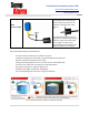
Your float switch has a three wire configuration, which can be used to make connections for either filling
or emptying.
- For “Normally Full” Operation, where the desire to activate a pump to Fill a tank, sump, or
vessel, use the Black and Blue Wires for connection, and cap the Brown wire.
- For “Normally Empty” Operation, where the desire to activate a pump to Empty a tank, sump, or
vessel, use the Black and Brown Wires for connection, and cap the Blue wire.
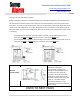
Installation #1
Without
Counterweight
The above diagrams demonstrate a
float switch utilizing the
counterweight included in the
package. A counterweight may not
be necessary in your particular
installation. In submersible pump
applications, a float switch can be
mounted as shown at left using only
a wire tie. The Tether Length
illustrated in the Figure can be
minimized to 3 inches from the float
switch ribbing.
(OVER TO NEXT PAGE)