
Use and Care Manual


12
5. Depress the trigger switch (Fig. 13). If inating, the air
pressure will appear on the gauge as the item is being
inated.
6. To turn the compressor OFF, press the trigger switch
(Fig. 13).
7. Remove the thread connector from the tire quickly,
and replace valve stem cap on tire, if required.
NOTE: The air compressor will stop automatically when
the desired pressure is reached. Please press trigger to
shut o the machine before removing the air chuck.
NOTE: If you disconnect the air chuck without pressing
the trigger to turn o the machine, the air compressor
will run an additional 30 seconds before shutting o
automatically.
mCAUTION! Connector may be hot. Use caution when
removing.
mWARNING! To avoid over-ination of tires, please check the
recommended tire pressure in the vehicle’s owner’s manual.
For bicycle tires, check markings on tire. Use a separate pressure
gauge for a more accurate reading.
mCAUTION! The LCD display must turn on before operating
the air compressor. Please read and understand the instructions
provided in the manual prior to operation.
Lock-On Function
The air compressor is equipped with a lock-on feature, which
is convenient for continuous inating for extended periods of
time.
1. To lock on, depress and hold the trigger switch (Fig. 13).
2. Release the trigger switch and the air compressor will
continue running.
3. To release the lock, press the trigger switch down to stop
(Fig. 13).
Duty Cycle
1. For household use only.
2. The air compressor is designed for occasional use.
Ination over a long period will overheat the air
compressor and may cause damage.
3. The air compressor should not operate for more than 5
minutes at a time, after which it must be switched o
and allowed to cool down for at least 10 minutes before
restarting.
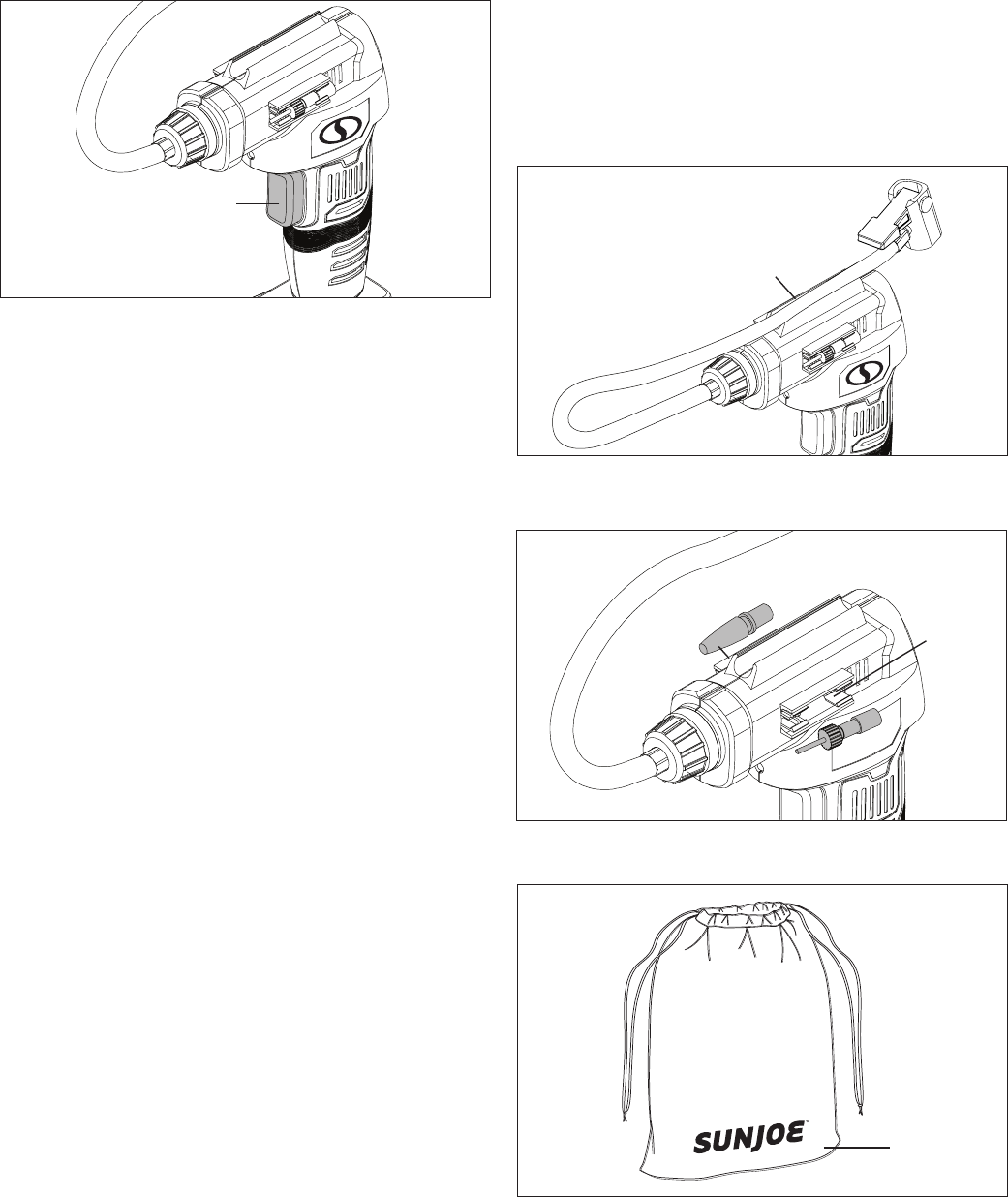
Storage
Air Hose + Adapters Storage
1. When the air compressor is not in use, press the hose into
the storage area on top of the tool (Fig. 14).
2. Adapters provided with the air compressor can be placed
in the storage area located on both sides (Fig. 15).
3. Store the tool and all accessories into the storage bag
(Fig. 16).
Fig. 13
Trigger switch
Fig. 14
Air hose
storage
Fig. 15
Adapter
storage
area
Fig. 16
Storage
bag