
Replacement Part List


Operation
Starting and Stopping
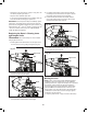
1. Slide the battery into the battery compartment until it
clicks to lock into position (Fig. 35).
2. To turn the grass trimmer + hedger ON, push and hold
the safety lock switch (located on the handle) forward
with your thumb and then squeeze the On/O switch with
your ngers. Once the tool is running, you can release the
safety lock switch (Fig. 36).
3. To turn the tool OFF, release the On/O switch (Fig. 36).
Adjusting the Telescoping Pole
This machine is equipped with a telescoping pole which can
telescope from 3.7 ft (1.1 m) to 5.3 ft (1.6 m). To adjust the
telescoping pole, follow the instructions below.
1. Disconnect the grass trimmer + edger from the power
supply by removing the battery from the compartment.
2. Unclip the telescoping lock to release the pole. Extend the
pole to the desired length (Fig. 37).
NOTE: Push poles toward each other to shorten the pole
or pull them away from each other to lengthen the pole.
Only extend the pole to the minimum length required to
reach the grass.
3. Lock the pole in position by closing the telescoping lock
(Fig. 38), and ensure that the pole is secured.
mWARNING! Failure to lock the telescoping lock as
directed could result in personal injury.
Adjusting the Auxiliary Handle
The grass trimmer + edger is equipped with an auxiliary handle
that can be adjusted and removed. Follow the instruction
below to operate the auxiliary handle.
mWARNING! Make sure the knob, bolt, and the screws
are xed into place after adjusting. Failure to lock any of them
as directed could result in personal injury or property damage.
To Remove the Auxiliary Handle
1. Disconnect the grass trimmer + edger from the power
supply by removing the battery from the compartment.
2. Screw the auxiliary handle knob and remove it with the
bolt, then the auxiliary handle can be pulled out (Fig. 39).
3. Re-assemble the auxiliary handle lock knob and the bolt
on (Fig. 40).
Fig. 35
Battery
Fig. 36
On/O switch
Safety lock
switch
Fig. 37
Pull Pull
Telescoping lock
Fig. 38
Telescoping lock
R
Fig. 39
Auxiliary handle
Auxiliary handle
lock knob
Bolt
R
Fig. 40
21