
Replacement Part List


28
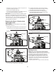
3. Lock the pole in position by closing the telescoping lock
(Fig. 64), and ensure that the pole is secured.
mWARNING! Failure to lock the telescoping lock as
directed could result in personal injury.
Adjusting the Auxiliary Handle
The hedge trimmer is equipped with an auxiliary handle that
can be adjusted and removed. Follow the instruction below to
operate the auxiliary handle
mWARNING! Make sure the knob, bolt, and the screws
are xed into place. Failure to lock any of them as directed
could result in personal injury or property damage.
To Remove the Auxiliary Handle
1. Disconnect the hedge trimmer from the power supply by
removing the battery from the compartment.
2. Screw the auxiliary handle knob and remove it and the
bolt, then the auxiliary handle can be pulled out (Fig. 65).
3. Re-assemble the auxiliary handle lock knob and the bolt
on (Fig. 66).
To Adjust the Position of the Auxiliary Handle
1. Disconnect the hedge trimmer from the power supply by
removing the battery from the compartment.
2. Remove the auxiliary handle knob, the bolt, and the
auxiliary handle. Use a screw driver to remove the two
screws that used to x the auxiliary handle loops. Remove
the loops from the pole (Fig. 67).
3. Re-assemble the auxiliary handle loops on the desired
spot on the pole by using the two screws, and put back
the auxiliary handle, the auxiliary handle lock knob and the
bolt (Fig. 67).
To Adjust the Angle of the Auxiliary Handle
1. Stop the hedge trimmer by releasing the On/O switch,
2. The auxiliary handle can be adjusted in -45°, 0°, 45°.
Rotate the handle lock knob to unlock the handle, and
then rotate the handle to the desired angle (Fig. 68).
3. Rotate the handle lock knob back to lock the handle in
position.
Fig. 64
Telescoping lock
R
Fig. 65
Auxiliary handle
Auxiliary handle
lock knob
Bolt
R
Fig. 66
R
Fig. 67
Auxiliary handle
Auxiliary
handle
lock knob
Bolt
Auxiliary
handle loop
Screws
Auxiliary
handle loop
R
Fig. 68
Removable
handle