
User Manual


19
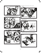
3. Remove the M6 bolt and sprocket cover from sprocket 1
then remove the auger belt from pulley 1 (Fig. 31).
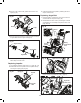
4. Disassemble the housing by removing the 6 housing bolts
(3 on each side) (Fig. 32).
5. Separate the blower assembly from the drive unit
(Fig. 33).
6. Unscrew pulley bolt, washer, 3 screws and pulley cover
then remove the pulley 1 and bushing from the blower
assembly (Fig. 34).
7. Disassemble the auger and impeller by removing the nuts
and bolts from the side of the auger housing (Fig. 35).
Fig. 30
Open motor cover
Fig. 31
Auger belt
Sprocket cover
M6 bolt
Sprocket
1
Pulley
1
Fig. 32
Housing bolt
(BLOWER ASSEMBLY) (DRIVE UNIT)
Fig. 33
Auger belt
(BLOWER ASSEMBLY)
(DRIVE UNIT)
Fig. 34
(BLOWER ASSEMBLY)
Pulley
1
Screw
Washer
Pulley
cover
Bushing
Bolt
Fig. 35
Nut + bolt
Impeller
Auger
Auger
housing