
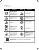
Replacement Part List

9
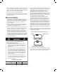
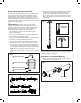
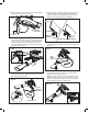
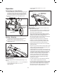
2. Slide the inlet cover lock button forward to disengage the
inlet cover. Hold the cover open (Fig. 8).
3. With the blower tube removed from the blower housing,
insert the "hooked" side end of the vacuum/mulcher tube
into the rear clip on the unit. Securely fasten the vacuum/
mulcher tube by pushing the "wedged" side end of the
vacuum/mulcher tube up until the lock button snaps into
the locked position (Fig. 9).
4. Insert the collection bag adaptor into the blower air outlet
until the collection bag is securely fastened (Fig. 10), then
clip the bag to the strap holder.
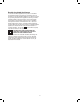
5. Press the button on the wheel assembly, then slide it onto
the lead rail. Adjust the wheel position by pressing the
button and sliding the wheel assembly up and down the
lead rail until the desired setting is reached (Fig. 11).
6. To remove the bag, press the tube release button and slide
the bag o of the unit. Unclip the bag from the strap holder
(Fig. 12).
7. To remove the vacuum/mulcher tube assembly, slide the
inlet cover lock button to unlock, then remove the tube
assembly from its housing (Fig. 13).
NOTE: It may be necessary to remove the blower tube or
vacuum/mulcher tubes to clear a blocked tube or impeller.
Make sure to disconnect the unit from the power supply
before attempting to clear any obstructions.
Fig. 8
Inlet cover
lock button
Inlet cover
Fig. 9
Rear clip +
Hook side
Wedged side
R
Fig. 10
Collection bag
Air outlet
Collection
bag adaptor
Fig. 11
Press button to adjust position
Lead rail
Wheel
Assembly
Button
R
Fig. 12
Tube
release
button
Fig. 13
Inlet cover
lock button