
User Manual


8
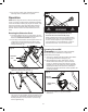
4. Slide the upper crank rod through the rubber ring located
on the middle frame (Fig. 11).
5. Slide the upper crank rod into the top of the crank rod
connector (Fig. 12).
6. Align the holes on the connector with the holes on
the upper crank rod, insert the thumbscrew and turn
clockwise to secure it (Fig. 13).
Discharge Chute Assembly
1. Position the chute deector over the discharge chute
and align them with the deector bolts, washers and the
deector knobs (Fig. 14).
2. Secure the deector bolts, washers and knobs. Make sure
the knobs are tightened (Fig. 15).
Fig. 10
Fig. 11
Upper crank rod
Rubber ring
Fig. 12
Upper crank rod
Lower crank
rod
Crank rod
connector
Fig. 13
Thumbscrew
Fig. 14
Deectorknob
Deectorbolt
Washer
Fig. 15