
Replacement Part List

Technical Data
Rated Voltage ..................................................120 V ~ 60 Hz
Motor ...............................................................13.5 amp
Max Water Inlet Temperature ..........................104ºF/40ºC
Max Water Inlet Pressure ................................0.7 MPa
Rated Flow ......................................................1.35 GPM
Max Flow .........................................................1.6 GPM
Rated Pressure ................................................1400 PSI
Max Pressure* .................................................1800 PSI
Detergent Tank Capacity .................................1 Gal (3.8 L)
High-pressure hose Length .............................25 ft (7.6 m)
Power Cord Length .........................................35 ft (10.7 m)
Weight .............................................................62.4 lbs (28.3 kg)
*Peak pressure at initial discharge; working pressure under typical load is 1400
PSI.
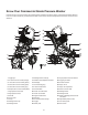
Unpacking
Carton Contents
• Lower handle frame + pressure washer assembly
• Upper handle frame + hose reel assembly
• Connecting hose
• Spray wand
• Trigger gun
• Oil measuring plug
• Five (5) Quick-Connect nozzles (0º, 15º, 25º, 40º and Soap)
• Needle clean-out tool (included with manual packet)
• Manuals with registration card
1. Carefully remove the pressure washer and check to see
that all of the above items are supplied.
2. Inspect the product carefully to make sure no breakage or
damage occurred during shipping. If you nd damaged or
missing parts, DO NOT return the unit to the store. Please
call the Snow Joe
®
+ Sun Joe
®
customer service center at
1-866-SNOWJOE (1-866-766-9563).
NOTE: Do not discard the shipping carton and packaging
material until you are ready to use your new electric
pressure washer. The packaging is made of recyclable
materials. Properly dispose of these materials in
accordance with local regulations.
IMPORTANT! The equipment and packaging material are not
toys. Do not let children play with plastic bags, foils, or small
parts. These items can be swallowed and pose a suocation
risk!
mWARNING! Do not connect to power supply until
assembly is complete. Failure to comply could result in
accidental starting and possible serious personal injury.
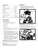
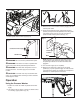
Assembly
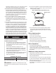
1. Slide the upper handle frame into lower handle frame,
then depress the small button at the end of the lower
handle frame, push and insert into upper handle until it
snaps securely into place (Fig. 1).
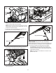
mIMPORTANT! Before starting, follow the instructions
below to remove the oil inlet nut on top of the pump and
replace with the oil measuring plug.
2. Flip up the pump cover to expose the oil inlet nut. Use a
wrench to loosen and remove the oil inlet nut by twisting it
counterclockwise (Fig. 2).
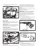
3. Insert the provided oil measuring plug and secure in place
by twisting it clockwise (Fig. 3).
Fig. 1
Upper handle
frame
Lower handle
frame
Push button
Fig. 2
Pump cover
Oil inlet
nut
7