
Use And Care Manual

9
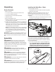
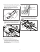
3. Starting at the tip, mount the chain drive links into the bar
groove, leaving a loop at the back of the bar. The chain will
loosely t until it is placed on the sprocket (Fig. 3).
NOTE: Make certain of the direction of the chain. If
the chain is mounted backwards, the saw will vibrate
abnormally and will not cut.
4. Hold the chain in position on the bar and place the loop
around the sprocket. Fit the bar ush against the mounting
surface so that the bar studs are in the long slot of the bar
and the adjusting pin is in the chain tension pin hole
(Fig. 4).
NOTE: If the adjusting pin will not reach the chain tension pin
hole, turn the chain tensioning screw counter-clockwise until
the pin hole aligns with the adjusting pin.
5. While keeping the bar and chain ush against the
mounting surface, adjust the chain tension as needed
by adjusting the chain tensioner screw with the supplied
at-tip blade screwdriver. Turn the chain tensioner screw
clockwise to tightening the chain, or counter-clockwise to
loosen the chain (Fig. 5).
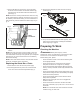
6. Replace the chain/sprocket end cover by inserting the rear
tab rst into the rear tab slot and position the cover over
the bar end. Tighten the end cover nut; leave the bar loose
enough to move slightly for tension adjustment (Fig. 6).
Fig. 3
Loop
Fig. 4
Sprocket
Bar studs
Chain tension pin hole
(with adjusting pin)
Fig. 5
Chain tensioner
screw
Blade screwdriver
Fig. 6
Rear
tab
End cover nut
Chain/sprocket
end cover