
Installation Guide


Installation Common To Electric Or NE Units
-
- 8 -
Leading the
vent through the
roof
Leading the
vent through the
wall
The Diffusor
Drain
Installation
Handling
Effluent
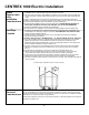
The vent stack (shown in diagram) should end
approximately 30” above the peak of the roof so that
it is less subject to downdraft. Where the pipe is
taken through the roof, a roof flashing may be
required to seal the installation. If you are in an area
where snow shear is a danger, you may wish to
install a heavier pipe around the vent pipe where it
exits from the roof. If you do choose to do this,
ensure that you seal the area between the pipes
with a waterproof substance to prevent leaks.
When it is necessary to lead the vent through a wall,
connect one 45° elbow on the vent outlet on the unit.
Using a hole saw or other appropriate tool, cut a
hole through the wall board behind the unit so that
the vent pipe can be inserted into the 45° elbow. Cut
a similar hole on the other side of the wall that is
slightly higher than the inner hole so that the vent
pipe will be angled upward at 45°. If installing
through an exterior wall, waterproof sealant will be
required around the vent pipe where it emerges from
the building.
The diffusor provided with the unit is a simple device
to be installed at the top of the vent stack with the
larger pipe protruding above the smaller. To install,
simply glue the diffusor vertically on the topmost
section of vent pipe. The diffusor design encourages
updraft, and discourages wind and weather from
going down the vent stack. We do not recommend
installing anything else on the top of the vent as it
could impede the venting. Unlike wind
turbines,
diffusors are less likely to freeze in winter, and are
more effective in calm weather.
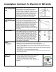
The safety drain must be connected as it will be required in all Centrex 1000 NE
installations or Centrex 1000 electric with ultra-low flush toilets.
- Remove the orange cap from one side of the overflow drain assembly.
- Place a 1” hose clamp over the end of the drain hose that will be connected to the
overflow drain assembly.
- Push the drain hose over the ribbed end of the over-flow drain and clamp with the 1”
SS hose clamp.
- Connect the 1” hose to an approved drainage facility.
- The safety drain is gravity fed. The drain hose must be below the level of the safety
drain in order to function.
The following are possible options to take care of the liquid :
- Feed into a lined pit filled with gravel and sand. Such a
recycling bed also ensures a closed loop system.
- Feed into a small cesspit or “French drain”.
- Plumb into an existing septic or holding tank line.
Installation should be in accordance with applicable local
regulations.