T N E M U C O D E L P M EXA Sun Blade™ 1500 Service, Diagnostics, and Troubleshooting Manual Sun Microsystems, Inc. 4150 Network Circle Santa Clara, CA 95054 U.S.A. 650-960-1300 Part No. 816-7564-10 April 2003, Revision A Send comments about this document to: docfeedback@sun.
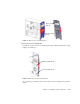
DIMM ejector levers (8) DIMM gold edge DIMM slots (4) DIMM3 DIMM2 DIMM1 DIMM0 DIMM FIGURE 11-1 DIMM Location and Identification Depending upon the configuration of your workstation, you can either add or replace memory. In either case, the new DIMMs must meet the Sun workstation requirements. TABLE 11-1 lists the acceptable DIMM pair configurations.
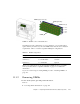
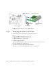
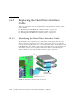
You can also view an animated version of these instructions by clicking on this film icon. 13.3.1 Identifying the Rear Fan The front and rear fans on the Sun Blade 1500 workstation are contained in green brackets. Both fans must be operating to adequately cool the components in a closed chassis. Both fans are connected to the motherboard with a cable that carries power and signal. FIGURE 13-14 shows the location of and identifies the rear fan.
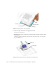
Smart card reader cable Smart card reader Drive rails Smart card reader bracket Connector SCR0 FIGURE 12-13 12.3.2 Smart Card Reader Location and Identification Removing the Smart Card Reader 1. Power off the system, open the chassis, and remove the bezel. Refer to: ■ ■ ■ “Powering Off the Workstation” on page 10-4 “Removing the Access Panel” on page 10-12 “Removing the Bezel” on page 10-14 2. Locate the smart card reader.
14.2.1 Identifying the DVD-ROM Drive Interface Cable The DVD-ROM has separate power and interface cables. The power cable is a Y cable that connects to the motherboard at IDE PWR and the other ends to the hard drives and DVD-ROM drive. The interface cable connects the DVD-ROM drive to the motherboard at IDE SEC. The interface cable is a 40-conductor ribbon cable that is routed through the chassis.FIGURE 14-5 shows the DVD-ROM drive interface cable connections.
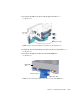
3. Disconnect the IDE power cables from the upper hard drive HDD0. See FIGURE 14-12. Connector IDE PWR IDE power cable FIGURE 14-12 Disconnecting the IDE Power Cable From the Hard Drive(s) 4. If installed, disconnect the IDE power cable from the lower hard drive HDD1. See FIGURE 14-12. 5. Disconnect the IDE power cable from the DVD-ROM drive. See FIGURE 14-13.
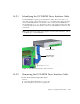
14.3 Replacing the Hard Drive Interface Cable This section describes removal and installation of the hard drive interface cables. Topics include: ■ ■ ■ 14.3.1 “Identifying the DVD-ROM Drive Interface Cable” on page 14-7 “Removing the DVD-ROM Drive Interface Cable” on page 14-7 “Installing the DVD-ROM Drive Interface Cable” on page 14-8 Identifying the Hard Drive Interface Cable The hard drives have separate power and interface cables. Both cables have two inline connectors to support up to two drives.
Catch Guide rails FIGURE 11-3 Pressing the Catch on the Rear Fan Bracket 4. Slide the duct up until it is flush with the edge of the rear fan bracket. See FIGURE 11-4. Duct flush with bracket FIGURE 11-4 Sliding the Duct Up 5. Flip the duct up and over to the back of the chassis, so that it is 180 degrees opposite of its original position. See FIGURE 11-5.
Bezel short tabs (2) Bezel mounting tabs (4) FIGURE 10-9 Bezel Location and Identification 3. Release the lower mounting tabs. Carefully move the lower pair of mounting tabs apart, and then push them forward slightly. See FIGURE 10-10. Middle mounting tabs (2) Lower mounting tabs (2) FIGURE 10-10 Releasing the Bezel Mounting Tabs As you do this, you should see the bottom of the bezel move slightly away from the chassis.
Latch End tabs (4) Center tab Locking ring Clips (2) FIGURE 11-15 Pressing Down on the Clip Latch b. Slide the clip to unhook the end opposite the latch. This relieves clip pressure. c. Rotate the clip away from the CPU fan and heatsink assembly and lift it off the locking ring. Set the clip aside. If removing clips separately, repeat from Step a for the other clip. See FIGURE 11-16.
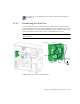
.3.1 Identifying the Battery FIGURE 11-23 shows the location of and identifies the battery. Battery clip Battery (BAT0) FIGURE 11-23 Battery Location and Identification TABLE 11-1 lists the battery specifications. TABLE 11-4 11.3.2 Battery Specifications Specification Value Voltage 3 VDC Type CR 2032 Removing the Battery 1. Power off the system, open and position the chassis.
PCI4 (66 MHz, 64-bit) PCI3 (33 MHz, 64-bit) PCI2 (33 MHz, 64-bit) PCI1 (33 MHz, 32-bit) PCI0 (33 MHz, 32-bit) FIGURE 11-34 Identifying the PCI Card Slots 3. Swing out the PCI card support. Squeeze the inside tabs together and swing the PCI card support out. See FIGURE 11-35.
Routing clip Routing clip Cables Power supply cables FIGURE 11-42 Removing Cables From the Routing Clips 9. Disconnect the power and signal cables. Disconnect the following power and signal cables from the corresponding motherboard connectors and set them out of the way of the motherboard. See FIGURE 11-41.
Pivot tab FIGURE 13-48 Removing the PCI Card Support Note – Do not use the chassis cross brace as a handle. Proceed to “Installing the PCI Card Support” on page 13-45. Note – Do not operate the workstation without the PCI card support installed. 13.7.3 Installing the PCI Card Support 1. Open the chassis. Refer to “Removing the Access Panel” on page 10-12 2. Identify where the PCI card support is to be installed. See FIGURE 13-46. 3. Install the PCI card support.
FIGURE 15-8 Reconnecting the Keyboard, Mouse, Monitor, and Network Connections 2. Reconnect any other external peripherals. 3. Power on those peripherals. Note – The monitor must be powered on before the system so that the monitor can communicate with the graphics accelerator when the system powers on. 4. Reconnect the power cord between the power source and the system power supply connector. See FIGURE 15-9.