Server User Manual
Manuals
Brands
Sun Microsystems Manuals
Switch
5000
311
312
313
314
315
316
317
318
319
320
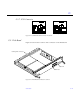
Connectors
G-5
G
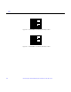
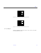
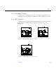
Figure G-6
CPU
Module
0
Connector
(288
Pin)
Location
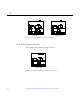
Figure G-7
CPU
Module
1
Connector
(288
Pin)
Location
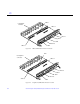
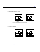
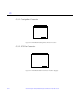
G.2
I/O
Board
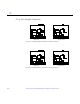
Figure G-8
and
Figure G-9
show
the
locations
of
the
connectors
on
the
SBus
I/O
and
Graphics
I/O
boards.
0
1
0
1
1
...
...
311
312
313
314
315
...
...
334