Sun Fire™ V440 Server Installation Guide Sun Microsystems, Inc. 4150 Network Circle Santa Clara, CA 95054 U.S.A. 650-960-1300 Part No. 816-7727-10 July 2003, Revision A Submit comments about this document at: http://www.sun.
Copyright 2003 Sun Microsystems, Inc., 4150 Network Circle, Santa Clara, California 95054, U.S.A. All rights reserved. Sun Microsystems, Inc. has intellectual property rights relating to technology embodied in the product that is described in this document. In particular, and without limitation, these intellectual property rights may include one or more of the U.S. patents listed at http://www.sun.com/patents and one or more additional patents or pending patent applications in the U.S.
Contents Preface 1. v Preparing for Installation 1 About the Parts Shipped to You Verify All Parts 2 Transfer Online Documentation Plan the Installation What Next 2.
Secure the Cords and Cables to the Cable Management Arm Install Optional Components 28 Connecting the Cords and Cables 29 Connect the Power Cords to the Server Connect Twisted-Pair Ethernet Cables Restore the Cabinet What Next 3.
Preface The Sun Fire V440 Server Installation Guide provides instructions, some background information, and reference material to help you install a new Sun Fire™ V440 server. Instructions in Chapters 1 and 3 assume that a system administrator who is experienced with the Solaris™ operating environment is performing the installation.
Using UNIX Commands This document might not contain information on basic UNIX® commands and procedures such as shutting down the system, booting the system, and configuring devices.
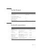
System Prompts Type of Prompt Prompt C shell machine-name% C shell superuser machine-name# Bourne shell and Korn shell $ Bourne shell and Korn shell superuser # ALOM system controller sc> OpenBoot firmware ok OpenBoot Diagnostics obdiag> Related Documentation Application Title Part Number Late-breaking product information Sun Fire V440 Server Product Notes 816-7733 Cabling and power-on overview Sun Fire V440 Server Setup: Cabling and Power-On 816-7734 Administration Sun Fire V440 S
Accessing Sun Documentation You can view, print, or purchase a broad selection of Sun documentation, including localized versions, at: http://www.sun.com/documentation Note – For important safety, compliance, and conformity information regarding the Sun Fire V440 server, see the Sun Fire V440 Server Safety and Compliance Guide, part number 816-7731, on the Documentation CD or online at the above location.
CHAPTER 1 Preparing for Installation This chapter includes a description of the components of the Sun Fire V440 server, a list of documents on the Documentation CD, and a set of questions that the system administrator must answer before installing the server software.
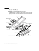
Verify All Parts ● Verify that you have received all the parts of your system. See the illustration below to identify most of the parts shipped with the system. (Not shown in the illustration is the RJ-45/DB-9 adapter, which is also shipped with the system.
Transfer Online Documentation The Sun Fire V440 Server Documentation CD is included in the ship kit. See the booklet included with the CD for instructions on transferring the documentation to disk or viewing the documentation directly from the CD.
Note – Be sure to use a supported version of the Solaris operating environment. See the Sun Fire V440 Server Product Notes for more information. What Next Install the server into a cabinet, following instructions in Chapter 2.
CHAPTER 2 Installing a Sun Fire V440 Server Into a 4-Post Cabinet This chapter shows you how to install a Sun Fire V440 server into a 4-post Sun™ StorEdge Expansion Cabinet or other Electronic Industries Association (EIA)-compliant 19-inch (48.26-cm) wide rack. If you are installing a Sun Fire V440 server into a 2-post rack, refer to the 2-post rackmounting instructions that are included on the Documentation CD in the Ship kit.
■ ■ ■ ■ ■ ■ “Secure the Cords and Cables to the Cable Management Arm” on page 25 “Install Optional Components” on page 28 “Connecting the Cords and Cables” on page 29 “Connect the Power Cords to the Server” on page 30 “Connect Twisted-Pair Ethernet Cables” on page 32 “Restore the Cabinet” on page 34 For a detailed list of 4-post cabinet requirements, turn to the section, “4-Post Cabinet Requirements” on page 52.
Inventory for 4-Post Rackmounting You need one 4-post rackmounting kit for each Sun Fire V440 server you intend to install into a cabinet. The 4-post rackmounting kit is included with the server. You also need this document and the Rack Alignment template from the ship kit.
The plastic bags of hardware contain screws and nuts that are shown below in actual size. 10-32 8-32 M6 M4 8-32 M6 10-32 Any screws not used for rackmounting are spares. Note – Bar nuts are required (but not included) for non-threaded cabinets. See the instructions provided with your cabinet for more information. Tools Required for Rackmounting ■ ■ ■ 8 Phillips No. 2 screwdriver (Use to tighten 10-32 and M6 screws.
Attach the Inner Glides to the Chassis ● Attach the inner glides to the chassis using four M4 screws for each inner glide. Position the straight end of each inner glide toward the front of the server. Align the second hole on the inner glide with the first hole on the chassis.
Prepare the Cabinet 1. Open and remove, if applicable, the front and back doors of the cabinet. See the instructions provided with your cabinet. 2. Stabilize the cabinet by extending its anti-tip legs or bolting the cabinet securely to the floor. See the instructions provided with your cabinet and read “4-Post Cabinet Requirements” on page 52. The following illustration shows two anti-tip legs. Note that some cabinets have only one such leg. 3. Remove the side panels from the cabinet, if applicable.
Locate the Mounting Holes ● Locate and mark the rack rail holes that you will use to attach each slide assembly. You can either count the holes on the vertical rack rails or use the Rack Alignment template included with your documentation set. Make sure that each slide assembly is installed at the same height front-to-back and side-to-side in the rack. The Rack Alignment template is four rack units (7.00 inch/17.78 cm) tall.
To use the Rack Alignment template, complete these steps: a. Place the Rack Alignment template over the right front vertical rack rail, then move the bottom of the template to the location on the rack rail where the bottom of the server will be located. Retainer screw hole Ra ck Al ig nm tenem T pl at e Mounting holes b. Adjust the Rack Alignment template until the mounting holes openings are centered on two holes in the rail and the retainer screw hole is visible.
Install the Slide Assemblies Be aware of the following guidelines. Caution – Ensure that you have stabilized the cabinet by extending its anti-tip legs or bolting the cabinet securely to the floor. ■ ■ Install the slide assemblies into the lowest available position. Install additional servers from the base up in the cabinet. 1. Use the Rack Alignment template to locate and mark mounting holes on the front vertical rack rails. See “Locate the Mounting Holes” on page 11. 2.
3. With the help of an assistant, position one slide assembly on the inside of the cabinet with the front (short) mounting bracket at the front of the rack. a. Use the holes you marked in Step 1. b. Make sure that the slide assembly is level front-to-back. 4. Using two screws for each bracket, attach the front mounting bracket to the front rail of the cabinet and attach the back (long) mounting bracket to the back rail of the cabinet.
6. If the depth of the rack is greater than 27.25 inches (69.21 cm), install a Phillips 8-32 screw and an 8-32 lock nut on each back mounting bracket. Fully tighten the lock nuts. 7. Make sure that each slide assembly is fully retracted into the cabinet.
Install the Server Into the Cabinet Caution – Before you install or remove the server from the cabinet, be sure the ! cabinet is stabilized so that it cannot move or tip forward. See the cabinet documentation for information about stabilizing the cabinet. ! Caution – The server is heavy. Two persons are required to move the server. Note – Make sure that each slide assembly is fully retracted into the cabinet and check that the ball-bearing runner on each slide assembly is all the way forward. 1.
3. Holding the server level, slide it evenly into the cabinet until the inner glides stop. Tip – Slide the server in and out of the cabinet slowly and carefully to ensure that the slide assemblies are working correctly and are free from obstructions.
4. Press the flat spring catch on each inner glide in order to slide the server the rest of the way into the cabinet. 5. Fully tighten the screws that attach the back brackets to the back rails.
6. Secure the server to the front rails using four M4, M6, or 10-32 screws, depending on your cabinet, to attach the brackets to the rack. What Next The next tasks are to install the cable management arm and to connect the power cords and Ethernet (RJ-45) cables.
Install the Cable Management Arm This procedure describes how to attach the cable management arm to a server that is already installed in a cabinet. You need the following components from the ship kit and the rackmounting kit to install the cable management arm and to connect the cords and cables: ■ ■ Cable management arm Ethernet (RJ-45) cable You also need two AC power cords, which are not supplied. AC power cords (2) (Not supplied in kit) Ethernet RJ-45 cable Cable management arm 1.
a. Go to the back of the cabinet. Locate the tab and mounting hole on the curved end of the left inner glide as viewed from the back. b. Locate the slot and captive screw on one end of the cable management arm. The slot and captive screw attach the arm to the inner glide. You can attach the end of the cable management arm containing the slot and captive screw to either the left or right inner glide, depending on where the cords and cables connect to the server.
c. Fit the slot of the cable management arm over the tab of the inner glide. Slide the slot over the tab until the captive screw aligns with the mounting hole on the inner glide. You may need to rotate the cable management arm flange containing the slot and captive screw so that you can fit the slot over the tab.
d. Tighten the captive screw on the cable management arm. 4. Attach the other end of the cable management arm to the slide assembly. a. Go to the slide assembly on the right side of the server as viewed from the back. b. Locate the barrel at the end of the slide assembly. c. Locate the bracket at the end of the cable management arm. The bracket has openings at the top and bottom.
d. Slide the cable management arm bracket over the barrel so that the bracket openings align with the barrel openings. You may have to rotate the bracket to align the bracket openings with the barrel openings. You may also have to release the Velcro straps on the cable management arm to make sliding the assembly into the rack easier. Cable management arm bracket Barrel e. Locate the speed pin on the end of the cable management arm. The speed pin secures the cable management arm to the slide assembly.
f. Insert the speed pin through the aligned openings of the bracket and the barrel and push the pin down firmly. Speed pin Secure the Cords and Cables to the Cable Management Arm This procedure illustrates how to secure the power cords and the Ethernet cable to the cable management arm. Your server might use additional cables. 1. Install the cable management arm on the server. See “Install the Cable Management Arm” on page 20.
2. Locate the oval cutouts in the center section of the cable management arm and the Velcro straps in the first and third sections. The cutouts and straps enable you to route the cables and cords and to secure them to the cable management arm. Upper lip Velcro straps Oval cutouts First section Velcro straps 3. Route the cords and cables between the upper and lower lips of the first section of the cable management arm.
5. Group the cords and cables and insert each group into the oval cutouts. Use both oval cutouts in the center section to route different groups of cords and cables through the cable management arm. For example, you can group the power cords and insert them into one oval cutout, and then group the other cables and insert them into the other oval cutout. Note – Do not insert the cords or cables into the round cutouts. Use those cutouts to access and manipulate the cords or cables.
Install Optional Components ● Install any optional components shipped with your system. If you ordered options that are not factory-installed, see the Sun Fire V440 Server Parts Installation and Removal Guide for installation instructions. Note – All internal components except disk drives must be installed by qualified service technicians only.
Connecting the Cords and Cables The following figure shows the Sun Fire V440 server back panel and identifies the AC power inlets and I/O ports. 1 2 3 4 5 6 7 Port Information 1 AC inlets Power cords connect to each AC inlet. Do not connect the cord to an AC outlet at this point. See “Connect the Power Cords to the Server” on page 30. 2 Serial port (ttyb) This port provides standard serial functionality. Note that the system controller serial management port is not a standard serial port.
Connect the Power Cords to the Server 1. Unlock and open the right system door. 2. Insert the system key into the system control keyswitch. Note that you have two sizes of system keys. The smaller key enables you to close the system door even while the key is in the system control keyswitch. The door cannot be closed with the larger key in the keyswitch. 3. Turn the system control keyswitch to the Standby position. Standby HDD 3 HDD 2 PS 0 PS 1 HDD 1 HDD 0 4.
5. Connect an AC power cord to each AC inlet at the back of the server. Do not connect the cords to AC power outlets at this point. You connect the cords to AC outlets during a later step, after you set up a system console device. AC 0 AC 1 AC 0 AC 1 CAUTION: In order to remove all power from this unit, disconnect all power cords.
Connect Twisted-Pair Ethernet Cables Connect a twisted-pair Ethernet (TPE) cable to one or both of the Ethernet ports on the back panel. Each network interface is capable of 10-Mbps, 100-Mbps, or 1000-Mbps operation depending on network characteristics. 1. Choose a network port, using the following table as a guide. Ethernet Port OBP Devalias Device Path 0 net0 /pci@1c,600000/network@2 1 net1 /pci@1f,700000/network@1 Select the correct TPE connector for the interface you are installing.
2. Plug in a Category-5 unshielded twisted-pair cable (which is included in your ship kit) to the appropriate RJ-45 connector. You should hear the connector tab snap into place. The cable length must not exceed 328 feet (100 meters). AC 0 AC 1 CAUTION: In order to remove all power from this unit, disconnect all power cords.
Restore the Cabinet See the instructions provided with your cabinet to complete these steps. 1. Replace the side panels, if applicable. 2. Replace the front and back doors, if applicable. What Next The next tasks are to set up a system console device, power on the server, and install the Solaris operating environment. See Chapter 3.
CHAPTER 3 Setup and Power-On Procedures This chapter tells you how to set up a system console device and how to power on the server. It also provides guidelines for installing the Solaris operating environment. Make sure that you have installed the Sun Fire V440 server into a cabinet and, if you have installed it into a 4-post cabinet, that you have routed cords and cables into the cable management arm (see Chapter 2) before following the instructions in this chapter.
The following section provides background information on connecting the server to a terminal server. This section is followed by instructions for setting up a terminal server, followed by instructions for setting up an alphanumeric terminal to access the system console, and then followed by instructions for setting up a tip connection from another Sun system. For more detailed information, see the Sun Fire V440 Server Administration Guide or the Sun Fire V440 Server Diagnostics and Troubleshooting Guide.
Terminal server 3 2 1 4 5 6 7 8 9 10 11 12 13 14 15 Straight-through cable 1 2 3 4 Patch panel 5 6 7 8 9 10 11 12 13 14 15 Patch cable to serial management port Sun Fire V440 server FIGURE 3-1 Patch Panel Connection Between a Terminal Server and a Sun Fire V440 Server If the pinouts for the serial management port do not correspond with the pinouts for the RJ-45 ports on the terminal server, you need to make a crossover cable that takes each pin on the Sun Fire V440 server seri
▼ How to Access the System Console via a Terminal Server The following procedure assumes that you are accessing the system console device by connecting a terminal server to the serial management port (SERIAL MGT) of the Sun Fire V440 server. For detailed information about system console options, see the Sun Fire V440 Server Administration Guide. 1.
2. Attach one end of the serial cable to the alphanumeric terminal’s serial port. Use an RJ-45 null modem serial cable or an adapter that is appropriate for your device. If you are using a laptop system or a terminal with a DB-9 connector, use an appropriate RJ-45/DB-9 adapter. Plug in this cable or adapter to the terminal’s serial port connector. 3. Attach the serial cable’s RJ-45 connector to the server’s serial management port (SERIAL MGT) on the ALOM card.
1. Make sure that the Sun system to which you are establishing the tip connection is powered on and active. 2. Connect the RJ-45 serial cable and RJ45/DB25 adapter. Use the cable and adapter to connect the other Sun system’s ttyb serial port to the Sun Fire V440 server’s serial management port (SERIAL MGT). Pinouts, part numbers, and other details about the serial cable and adapter are provided in the Sun Fire V440 Server Parts Installation and Removal Guide. 3.
Prepare to Configure the Primary Network Interface The following instructions assume that you have chosen a network port and have installed an Ethernet cable, as instructed in the section, “Connect Twisted-Pair Ethernet Cables” on page 32. Note that some of these steps are optional, depending on how you want to configure the network. Optional steps are indicated by italics. 1. Choose a host name for the server and make a note of it.
During installation of the Solaris operating environment, the software automatically detects the system’s on-board network interfaces and any installed PCI network interface cards for which native Solaris device drivers exist. The installation program then asks you to select one of the interfaces as the primary network interface and prompts you for the information you gathered.
▼ How to Power On via the Power Button 1. Make sure that your system console device is turned on and active. 2. Turn on power to any peripherals and external storage devices. Read the documentation supplied with the device for specific instructions. 3. Unlock and open the right system door, as viewed from the front of the system. 4. Insert the system key into the system control keyswitch and turn the system control keyswitch to the Diagnostics position.
Note – Connect each cord to a separate circuit to maximize system availability. The Standby Available LEDs on the power supplies are lit, indicating that power is being supplied to the system. As soon as you plug in the power cord, several boot messages from the ALOM software are displayed on your system console device. The ALOM boot messages end with the ALOM prompt: sc> 6. At the ALOM prompt (sc>), enter the following command: sc> console The system will prompt you to create an administrator password. 7.
2. Turn on power to any peripherals and external storage devices. Read the documentation supplied with the device for specific instructions. 3. Connect the Sun Fire V440 server’s outlet plug of each power cord to the power sequencer in the cabinet (if your type of cabinet includes one), to a grounded outlet strip, or to a grounded AC power outlet. Note – Each outlet must connect the server to a 15A circuit for North America and Japan, and to a 10A or 16A circuit for Europe.
6. At the ALOM sc> prompt, type the poweron command: sc> poweron The ALOM software then prompts you to enter a new administrative password. 7. When prompted, enter and then confirm a new administrative password. Once again, the ALOM sc> prompt is displayed. 8. At the ALOM sc> prompt, again type the poweron command: sc> poweron The poweron command is executed and the sc> prompt is again displayed. You must complete the next step quickly, before the ALOM 60-second timeout expires.
Install the Solaris Operating Environment and Additional Software You must have set up a system console device before you can install the Solaris operating environment. See the section, “Set Up a System Console Device” on page 35. Be sure that you are using the Solaris operating environment supported by the Sun Fire V440 server. See the Sun Fire V440 Server Product Notes for additional information.
5. Run the SunSM Install Check tool to validate installation configuration. The tool identifies unsupported firmware and hardware configurations, identifying conflicts with configuration rules. The tool also ensures that your firmware is current and that you have all required patches installed. The URL for obtaining this tool is: http://sunsolve.sun.com/pub-cgi/show.pl?target=installcheck/installcheck What Next The Sun Fire V440 server is now ready for use and, if you desire, additional configuration.
APPENDIX A Background and Reference This appendix includes background and reference information that can help you with installation of your Sun Fire V440 server. All of the information in this appendix is related directly to instructions in this guide. System LEDs As you install your Sun Fire V440 server, be aware of several system status LED indicators on both the front and back panels.
From left to right, system status LEDs operate as described in the following table. TABLE A-1 System Status LEDs Name Description Locator This white LED is lit by Sun Management Center or ALOM software, or by Solaris command, to locate a system. Service Required This amber LED lights to indicate that the system hardware or software has detected a system fault. System Activity This green LED lights when the AC power is available and the operating system is running.
Further details about the diagnostic use of LEDs are discussed separately in the Sun Fire V440 Server Diagnostics and Troubleshooting Guide. Serial Port Connector Accessible from the back panel of the Sun Fire V440 server is a DB-9 connector labeled ttyb that serves as a single, general-purpose serial port.
4-Post Cabinet Requirements The server is designed so that you can install it into a 72-inch (184-cm) tall Sun StorEdge Expansion cabinet or other EIA-compliant industry-standard cabinet that meets the requirements listed in the following table. You need a Sun rackmounting kit for each server that you rackmount. Note – The server is fully serviceable in a 4-post cabinet when it is extended on its slide assemblies.
TABLE A-4 4-Post Cabinet Requirements (Continued) Cabinet Feature Requirement Airflow The server operating airflow is 92 cfm, regardless of ambient air and altitude. This airflow provides appropriate cooling up to 104o F (40o C) and 10,000 feet (3000 meters). For proper ventilation of the server, the front and back doors must comply with the following minimum open area requirements. • 60 percent of the area of the front door that is directly in front of the server must be open.
54 Sun Fire V440 Server Installation Guide • July 2003