
Server User Manual
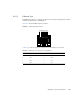
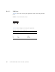
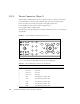
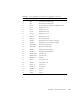
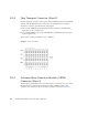
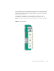
Table Of Contents
- Sun Netra™ CP3250 Blade Server User’s Guide
- Contents
- Figures
- Tables
- Preface
- Overview
- Hardware Installation and Service
- 2.1 Safety and Tool Requirements
- 2.2 Installing the Blade Server
- 2.3 Service Procedures
- 2.3.1 Hot-Swapping the Netra CP3250 Blade Server
- 2.3.2 Powering Off the Netra CP3250 Blade Server
- 2.3.3 Removing the Netra CP3250 Blade Server
- 2.3.4 Powering On the System
- 2.3.5 Automatic Power-Off Events
- 2.3.6 Servicing DIMMs
- 2.3.7 Installing the Optional Compact Flash Card
- 2.3.8 Installing Optional AMC
- 2.3.9 Adding or Replacing the Battery
- 2.3.10 Changing Jumper Settings
- 2.3.11 Checking DIP Switch Settings
- 2.3.12 Resetting the Netra CP3250 Blade Server
- Hardware Architecture
- Software Configuration
- Configuring and Using BIOS Firmware
- 5.1 About BIOS Settings
- 5.2 Changing the Configuration of a BIOS Menu Item
- 5.3 Setting the Boot Device Using BIOS Setup Screens
- 5.4 Setting Supervisor and User Passwords
- 5.5 Resetting the System Time and System Date
- 5.6 Updating the BIOS
- 5.7 Secondary BIOS Image
- 5.8 Perform a Live Firmware Upgrade
- 5.9 Power-On Self-Test
- 5.10 Changing POST Options
- BIOS Screens
- Physical Characteristics
- ShMM CLI and Commands
- Index
Appendix B Physical Characteristics B-9
Zone 3 connector pinouts are presented from the point of view of the ATCA blade,
meaning that TX means the ATCA blade is the signal source and the ARTM is the
signal receiver. Similarly RX means the ATCA blade is the signal receiver and the
ARTM is the signal source.
The “reserved” pins indicate connector pins that are currently reserved for
compatibility to all ARTMs. Do not connect signals to reserved pins. The “no
connect” indicates pins that should not be connected by the Sun Netra CP3250 blade
server.
FIGURE B-6 Zone 3 Connector