
Server User Manual
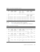
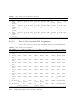
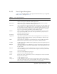
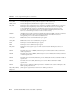


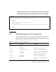
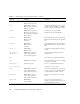
Table Of Contents
- Sun Netra™ CP3250 Blade Server User’s Guide
- Contents
- Figures
- Tables
- Preface
- Overview
- Hardware Installation and Service
- 2.1 Safety and Tool Requirements
- 2.2 Installing the Blade Server
- 2.3 Service Procedures
- 2.3.1 Hot-Swapping the Netra CP3250 Blade Server
- 2.3.2 Powering Off the Netra CP3250 Blade Server
- 2.3.3 Removing the Netra CP3250 Blade Server
- 2.3.4 Powering On the System
- 2.3.5 Automatic Power-Off Events
- 2.3.6 Servicing DIMMs
- 2.3.7 Installing the Optional Compact Flash Card
- 2.3.8 Installing Optional AMC
- 2.3.9 Adding or Replacing the Battery
- 2.3.10 Changing Jumper Settings
- 2.3.11 Checking DIP Switch Settings
- 2.3.12 Resetting the Netra CP3250 Blade Server
- Hardware Architecture
- Software Configuration
- Configuring and Using BIOS Firmware
- 5.1 About BIOS Settings
- 5.2 Changing the Configuration of a BIOS Menu Item
- 5.3 Setting the Boot Device Using BIOS Setup Screens
- 5.4 Setting Supervisor and User Passwords
- 5.5 Resetting the System Time and System Date
- 5.6 Updating the BIOS
- 5.7 Secondary BIOS Image
- 5.8 Perform a Live Firmware Upgrade
- 5.9 Power-On Self-Test
- 5.10 Changing POST Options
- BIOS Screens
- Physical Characteristics
- ShMM CLI and Commands
- Index

Appendix B Physical Characteristics B-13
B.3.5.5 Zone 3 Signal Descriptions
TABLE B-10 provides descriptions of the signals listed in the Zone 3 pin assignment
tables (
TABLE B-6 through TABLE B-9).
TABLE B-9 Zone 3 Signal Descriptions
Signal Name Description
IPMI_SCL_L IPMI bus clock signal, as defined in AMC.0 specification. RTM shall have a pull-up
resistor for this signal as indicated in AMC.0 specification.
IPMI_SDA_L IPMI bus data signal, as defined in AMC.0 specification. RTM shall have a pull-up
resistor for this signal as indicated in AMC.0 specification.
PS0#, PS1# Active low RTM present signal.PS0# shall be tied to logic GND on the ATCA blade, PS1#
shall be pulled up to 3.3V Management Power on the ATCA blade, PS0# and PS1# shall
be connected through diode on RTM, exactly as defined in AMC.0 specification. PS1# is
last mate on Power connector and PS0# is on the opposite end of the set of connectors.
Logic low on PS1# indicates that RTM is present and fully inserted.
Enable# When low indicates to RTM that it is fully inserted and that MMC can start execution.
Logic high shall keep MMC in reset state. This signal shall have a pull-up resistor as
indicated in AMC.0 specification.
Shelf_GND Frame/Chassis Safety Ground.
Logic_GND (Logic 0vdc). Logic Ground- Common return for Management Power Payload Power,
reference potential for single-ended logic signaling, and shielding for differential pair
signals in the AMC Connector.
12VPP 12V Payload Power, enabled after successful E-keying, following AMC.0 specification.
RTM shall meet requirements posted for payload power in AMC specification.
3.3V_MP 3.3V Management Power. RTM shall meet requirements posted for management power in
AMC.0 specification.
RTM_RX AMC Extended Options receive differential pair signals. Note that this specification takes
ATCA Blade perspective, which means that RX signals are driven by RTM and received
by ATCA Blade.
RTM_TX AMC Extended Options transmit differential pair signals. Note that this specification
takes ATCA Blade perspective, which means that TX signals are driven by ATCA Blade
and received by RTM.
SAS_TX SATA/SAS transmit differential pair signals.
SAS_RX SATA/SAS receive differential pair signals.
Serial 0 RS-232 Serial Signals, Transmit, Receive, Clear to Send, Request to Send, Data Terminal
Ready, and Data Set Ready.
LAN0 10/100/1000BASE-T signals.
LAN0_CTV 10/100/1000BASE-T transformer Center Tap signal, which could be used to terminate
center tap of transformers, if they are placed on RTM. This signal is applicable if Ethernet
PHY is located on ATCA blade, while transformers are located on RTM.