
Server User Manual
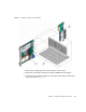
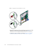


Table Of Contents
- Sun Netra™ CP3250 Blade Server User’s Guide
- Contents
- Figures
- Tables
- Preface
- Overview
- Hardware Installation and Service
- 2.1 Safety and Tool Requirements
- 2.2 Installing the Blade Server
- 2.3 Service Procedures
- 2.3.1 Hot-Swapping the Netra CP3250 Blade Server
- 2.3.2 Powering Off the Netra CP3250 Blade Server
- 2.3.3 Removing the Netra CP3250 Blade Server
- 2.3.4 Powering On the System
- 2.3.5 Automatic Power-Off Events
- 2.3.6 Servicing DIMMs
- 2.3.7 Installing the Optional Compact Flash Card
- 2.3.8 Installing Optional AMC
- 2.3.9 Adding or Replacing the Battery
- 2.3.10 Changing Jumper Settings
- 2.3.11 Checking DIP Switch Settings
- 2.3.12 Resetting the Netra CP3250 Blade Server
- Hardware Architecture
- Software Configuration
- Configuring and Using BIOS Firmware
- 5.1 About BIOS Settings
- 5.2 Changing the Configuration of a BIOS Menu Item
- 5.3 Setting the Boot Device Using BIOS Setup Screens
- 5.4 Setting Supervisor and User Passwords
- 5.5 Resetting the System Time and System Date
- 5.6 Updating the BIOS
- 5.7 Secondary BIOS Image
- 5.8 Perform a Live Firmware Upgrade
- 5.9 Power-On Self-Test
- 5.10 Changing POST Options
- BIOS Screens
- Physical Characteristics
- ShMM CLI and Commands
- Index

Chapter 2 Hardware Installation and Service 2-15
■ A telnet utility (Connect to the proper port on a Network Terminal Server to
which the Sun Netra CP3250 blade server is connected.)
■ Another suitable serial communications program on the system console
For example, if you are using a UNIX system as the system console, at the UNIX
prompt in a command tool or shell tool, or serial port A, type:
2.2.4.2 Connecting Cables to the System Console Not Running the
Solaris OS
1. Connect a serial cable to the serial console port on the front panel of the Sun
Netra CP3250 blade server (
FIGURE 2-4) or the Netra CP32x0 rear transition
module.
2. Connect the other end of the serial cable to the serial port of the system serving
as the system console.
3. Set the serial communications settings to 9600 baud, 8 bit, 1 stop bit, no parity,
and no handshake.
2.2.4.3 Netinstall Boot Device Map
TABLE 2-2 provides a map of netinstall boot devices. You may need this information
to understand which MAC address is associated with the system IP address on the install
server.
For example, the Base Fabric interface is connected to the switch model-number in
slot 8 of the ATCA shelf. To install to this device, select the xxx Ethernet interface
from the BIOS setup menus.
# tip -9600 /dev/ttya
TABLE 2-2 Netinstall Boot Device Table
MAC Address Solaris
Device
Hardware
Device Connects to...
Switch Slot
Connection
00:14:4f:xx.yy.zz+0 bge0 (BMC5715C) Base Fabric 0 Slot 7
00:14:4f:xx.yy.zz+1 bge1 (BMC5715C) Base Fabric 1 Slot 8
00:14:4f:xx.yy.zz+2 bge2 (MCP55)and
(BCM5715C)
mgtA (front panel)
00:14:4f:xx.yy.zz+3 bge3 (MCP55)and
(BCM5715C)
mgtB (rear panel)