Virtual Tape Library VTL Value Hardware Installation Guide Sun Microsystems, Inc. www.sun.com Part No. 316196101 Aug 2007, Revision A EC000066 Submit comments about this document at: glsfs@sun.
Copyright 2007 Sun Microsystems, Inc., 4150 Network Circle, Santa Clara, California 95054, U.S.A. All rights reserved. Sun Microsystems, Inc. has intellectual property rights relating to technology that is described in this document. In particular, and without limitation, these intellectual property rights may include one or more of the U.S. patents listed at http://www.sun.com/patents and one or more additional patents or pending patent applications in the U.S. and in other countries.
Revision History Short Name Part Number Dash Date VTL Value Hardware Installation Guide 316196101 A August 2007 Revision History Comments iii
iv VTL Value Hardware Installation Guide • Aug 2007
Contents About this book ix Using this book ix Taking advantage of this book’s hypertext features x Understanding the conventions used in this book x Using the Sun StorageTek Customer Resource Center (CRC) to obtain the latest information and supporting resources xi 1.
Installing the cable management arm ▼ Attaching the Outer Rail Extension Routing and connecting cables ▼ Installing data and power cables Starting the VTL appliance 2.
E.
viii VTL Value Hardware Installation Guide • Aug 2007
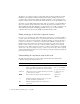
About this book This book describes the installation and initial configuration processes specific to the Sun StorageTek VTL Value appliance. In VTL Value deployments, it supersedes the Sun Fire™ X4500 Server Installation Guide (819-4358-11) that ships with the X4500 platform. While the VTL Value appliance hardware is almost identical to the X4500, it has been specially preconfigured to host Virtual Tape Library software on the Solaris operating system.
The chapters are organized to reflect top-level tasks. The first chapter details the physical installation of the appliance hardware, including rack mounting, cabling, and power up procedures. The second chapter explains the initial configuration of the operating system software and network and some basic checks that should be run on a newly installed system. Appendices provide additional information that, while not essential to a normal installation, may prove useful in special circumstances.
Using the Sun StorageTek Customer Resource Center (CRC) to obtain the latest information and supporting resources The Sun StorageTek Customer Resource Center stores the latest documentation, software updates, and licensing resources for VTL Value solutions. Always check the CRC for updates to this document before proceeding. Documents distributed on CDROM may not reflect the latest changes to VTL hardware, software, and services. You must have an account to use the CRC.
xii VTL Value Hardware Installation Guide • Aug 2007
C H A PT E R 1 Installing VTL Value hardware This chapter describes the process of physically installing the VTL Value appliance and applying power. The tasks break down as follows: This chapter contains procedures for: ■ “Installing the VTL Value appliance in an equipment rack” on page 1 (if a rack is used) ■ “Cabling” on page 16 ■ “Starting the VTL appliance” on page 22.
INSTALLING THE VTL VALUE APPLIANCE IN AN EQUIPMENT RACK ▼ Obtaining required tools, personnel, and materials 1. Make sure that the selected rack meets the following specifications: ■ The rack has four posts, with a mounting at both front and rear (two-post racks are not compatible with the VTL Value slide-rails). ■ The horizontal opening and unit vertical pitch of the rack conform to ANSI/EIA 310-D-1992 or IEC 60927 standards.
INSTALLING THE VTL VALUE APPLIANCE IN AN EQUIPMENT RACK ■ Label the hard disk drives in slots 2 to 46 and then remove them (you will reinstall the drives in their original slots using the labels as a guide). Do not uninstall the fan trays or the bootable drives in slots 0 and 1. 6. If a mechanical lift is available, make sure that at least three people are on hand to install the server in the rack.
INSTALLING THE VTL VALUE APPLIANCE IN AN EQUIPMENT RACK 3. Push the slide-rail lock (A below) to release the inner rail, and start to pull the inner rail out of the middle rail (B). A B D E C 4. Continue to pull the inner rail out of the middle rail (C above) until it contacts the internal stop (D). 5. Press the Push Here button on the green mounting-bracket release (E above), and pull the mounting bracket free of the middle/outer rail assembly. 6. Repeat for the remaining slide-rail assembly.
INSTALLING THE VTL VALUE APPLIANCE IN AN EQUIPMENT RACK 1. Position the inner rail (A below) against the chassis with the slide-rail lock (B) at the front. E D C C C A B 2. Align the three pairs of keyed openings on the inner rail with the three pairs of locating pins on the side of the chassis (C above). 3. While pressing the rear of the rail against the side of the chassis, push the rail toward the rear of the chassis (D above) until the rail clip (E) locks into place with an audible click. 4.
INSTALLING THE VTL VALUE APPLIANCE IN AN EQUIPMENT RACK 1. Before you start, select the lowest possible position in the rack, and deploy the rack’s anti-tilt bar. A top-heavy system tips over easily. So always load equipment into a rack from the bottom up and always place the heaviest equipment as low as possible. Always use the anti-tilt bar to keep the rack from tipping during installation. See the service label on the VTL Value appliance cover and/or the label on the rack. 2.
INSTALLING THE VTL VALUE APPLIANCE IN AN EQUIPMENT RACK 4. At the rear of the rack, use tape (G below) or a pin to temporarily mark the mounting hole (H) that corresponds to the mounting hole that you selected on the front. G 4U H 5. Repeat steps 2-4 for the remaining middle/outer rail. Next task: “Attaching the outer/middle rail assembly to the rack” on page 8.
INSTALLING THE VTL VALUE APPLIANCE IN AN EQUIPMENT RACK ▼ Attaching the outer/middle rail assembly to the rack 1. Before you begin, push the middle rail into the corresponding outer rail so that the ends are more or less flush. To do this, release the spring-activated slide-rail lock (A below) by pushing twice in the direction shown (B), then telescope the middle rail into the outer rail (C): B A C D 2.
INSTALLING THE VTL VALUE APPLIANCE IN AN EQUIPMENT RACK 3. Insert the oval-shaped neck of a temporary installation pin (E below) into the ovalshaped hole in rear mounting bracket of the outer slide-rail (F), and turn the pin clockwise 90 degrees, so that the pin locks into place in the 3 o’clock position. E F Temporary installation pins are packed in a plastic bag, with the slide-rail hardware. 4.
INSTALLING THE VTL VALUE APPLIANCE IN AN EQUIPMENT RACK 5. If the rack has threaded mounting holes in the rack posts, insert the correct, metric or standard mounting screws through the slide-rail brackets and into the threaded holes. The Sun™ Rack 1000 hardware uses metric screws. 6. If your rack does not have threaded mounting holes, insert the mounting screws through both the slide-rail brackets and rack posts, and then secure them with caged nuts. 7.
INSTALLING THE VTL VALUE APPLIANCE IN AN EQUIPMENT RACK ▼ Adjusting and securing middle/outer slide rails 1. Once both slide rails are loosely fastened at the front, insert the slide-rail spacing tool/rack installation aid (A below) into the outer rail brackets at the front of the rack (B). A B C 2. Hold the slide-rail spacing tool in place as you tighten all four front screws with a #2 Phillips screwdriver (C above).
INSTALLING THE VTL VALUE APPLIANCE IN AN EQUIPMENT RACK 4. At the rear of the rack, hand-tighten a screw in each of the bottom holes on the outer rail brackets (D below). F E D 5. Once the bottom screw is started, replace the installation pins at the top (E above) with hand-tightened screws (F).
INSTALLING THE VTL VALUE APPLIANCE IN AN EQUIPMENT RACK 6. Once both slide rails are loosely fastened at the rear, insert the slide-rail spacing tool into the outer rail brackets (D below). D E F 7. Hold the spacing tool in place (E above) as you tighten all four rear screws with a #2 Phillips screwdriver (F). The spacing tool should be a snug fit and might require pressure to ensure that it is fully engaged with the left and right slide rails. 8.
INSTALLING THE VTL VALUE APPLIANCE IN AN EQUIPMENT RACK Caution – To reduce the risk of serious personal injury or equipment damage, use a mechanical lift when mounting the server in the rack. If a lift is not available, remove components as described in the section “Obtaining required tools, personnel, and materials” on page 2 and following. 1. Pull the middle rails out from the outer rails, past the internal stop, so that the middle rails are about 1.
INSTALLING THE VTL VALUE APPLIANCE IN AN EQUIPMENT RACK 4. Using a level (D above), align the server with the rails, and insert the inner rails into the middle rails at the correct angle (E below). E 5. Have an assistant stand at the rear of the rack. 6. As you push the server into the rack, the assistant makes sure that the inner rails are engaged with the ball-bearing retainers (F below) and sliding on the bearings on both slide rails.
CABLING Caution – To prevent damage to the server or physical injury, if you are using a lift, keep the lift under the server. If you are manually installing the server, hold handles on each side of the server. 9. Test the operation of the slide-rails by slowly pulling the server out of the rack until the slide-rails reach their stops. 10. Test the operation of the slide-rails by pushing the server back into the rack until it reaches the internal stops. 11.
CABLING Note – References to “left” or “right” in the following procedures assume that you are facing the rear of the equipment rack. ▼ Attaching the Outer Rail Extension 1. Unpack the cable management arm (CMA) parts, and take them to the rear of the equipment rack. A B C 2. Pull out the captive thumbscrew (A above) and insert the outer rail extension to the right outer rail. 3. Insert the extension as far as it will go while aligning the captive thumbscrew with the hole in the outer rail (B above).
CABLING 6. Align the CMA-to-chassis bracket with the mounting holes in the right side of the server, and hand tighten the upper and lower screws (D and E below). D E F 7. Using a #2 Phillips screwdriver, tighten all three screws. Access the lower screw using the hole provided (F above). 8. Fold the cable management arm (CMA) back on itself (G below).
CABLING 9. Push the CMA hinge plate (H above and below) into the outer rail extension (J below) until the captive thumbscrew on the hinge plate (K) aligns with the hole in the outer rail extension (L). J H L K 10. Tighten the captive thumbscrew (K above) to secure the cable management arm (CMA) to the rail extension.
CABLING 11. Placing your hand under the CMA for support, fit the two pins (M, N below) into the keyholes in the CMA-to-chassis bracket (P, Q) and rotate CMA towards you until it seats with an audible snap (R). Q P M N R Next task: “Routing and connecting cables” on page 20.
CABLING 2. Route power, SAN, and LAN cables to the server through the CMA cable hangers (B below). You need to route the following cables: ■ one Ethernet LAN cable for the NETMGT port ■ up to four Ethernet LAN cables for the LAN ports (NET0, NET1, NET2, and NET3). ■ optical Fibre Channel cables for each SAN client (backup server). A B 3. Connect the power cords to the connectors on the power supplies, and secure them to the chassis using the clips provided (C below).
STARTING THE VTL APPLIANCE 5. Route Fibre Channel Storage Area Network (SAN) cables to the host bus adapters (W above), but do not connect them at this time. Wait to connect Fibre Channel cables until after the Fibre Channel interfaces have been zoned to hosts. 6. Inspect the attached cables for binding or kinks, and make sure that the CMA extends easily and does not bind in the slide-rails. Adjust the cable hangers and CMA as required. 7.
STARTING THE VTL APPLIANCE 1. To apply standby power and start the service processor, plug the two VTL appliance power cords in to grounded, 200-240 VAC power outlets. The startup process begins. It may take up to 58 seconds. When the service processor is up and the system is standing by, the OK LED on the front panel (A below) blinks, as does the Enclosure Status OK LED on the system controller (B).
STARTING THE VTL APPLIANCE 2. Once standby power is on, start the VTL server. Use a stylus to press and release the recessed main power button on the server front panel (C below). The VTL appliance ships with a pre-configured Solaris operating system, so you do not have to do any additional configuration before applying main power. When the server is up and running on main power, the OK LED (D) stops blinking and stays lit. C D Next task: “Setting up the VTL Value ILOM service processor” on page 25.
C H A PT E R 2 Setting up the VTL Value ILOM service processor The Sun StorageTek VTL Value appliance is implemented on a Sun Fire X4500 server platform that has been specially configured for tape virtualization. Much of the configuration of the base X4500 server has already been done at the factory. You merely need to set the IP address of the VTL Value Integrated Lights Out Manager (ILOM) service processor.
CHANGING THE IP ADDRESS OF THE ILOM SP ■ A Simple Network Management Protocol (SNMP) interface supports network management using SNMP versions 1, 2c, or 3. ■ A web server supports Remote Console operations. The server provides a browseraccessible ILOM graphical user interface (GUI) and supports VTL Value console redirection. By downloading a Java application from the ILOM web interface, users can access the Solaris desktop on a remote VTL Value appliance using a local keyboard, monitor, and mouse.
CHANGING THE IP ADDRESS OF THE ILOM SP ■ two standard Ethernet cables and a hub A 3. Obtain passwords for the VTL Value ILOM and for Solaris. Default passwords are posted on the Sun StorageTek Customer Resource Center at Current Products > Appliance > Virtual Tape Library (VTL). If the defaults have already been changed, obtain the replacement passwords from the Sun engagement team or from a customer system administrator. 4. Open a web browser to the IP address of the VTL appliance (B below).
CHANGING THE IP ADDRESS OF THE ILOM SP ▼ Changing the IP address of the ILOM 1. When the Integrated Lights Out Manager page appears, press the Configuration button (A below). A B 10.0.0.100 C 255.255.255.0 D 2. On the Network Settings panel, click the Use the Following IP Address radio button (B above). 3. Change the default IP Address and Subnet Mask shown to the IP address and subnet mask specified by the customer (C above). 4. Press Save (D above). 5.
CHANGING THE ILOM PASSWORD Changing the ILOM password The Integrated Lights Out Manager (ILOM) service processor on the VTL Value appliance ships with a well-known default password that facilitates deployment and initial configuration. Once the initial configuration is complete, you must change this password to something that is more secure. Use the procedure below. ▼ Resetting the default ILOM password 1. On the Integrated Lights Out Manager web GUI page, press the User Management button (A below).
CHECKING THE HEALTH OF THE INTERNAL STORAGE SYSTEMS 4. When the edit dialog appears, enter the new password in the New Password and Confirm New Password fields (D below). D E F 5. Press Save (E above) and then Close (F). Next task: “Checking the health of the internal storage systems” on page 30.
CHECKING THE HEALTH OF THE INTERNAL STORAGE SYSTEMS ▼ Accessing the Solaris desk top via the ILOM 1. On the Integrated Lights Out Manager (ILOM) page, press the Remote Control button (A below). A 2. On the Launch Redirection panel, click the radio button for 8‐ or 16‐bit resolution (B below), and press Launch Redirection (C). B C Java starts, downloads files, and launches the Java console.
CHECKING THE HEALTH OF THE INTERNAL STORAGE SYSTEMS 3. When the download dialog appears, click the Open with radio button, and select Java(TM) Web Start Launcher from the list (D below). Then press OK (E). D E The jnlp file launches the Sun ILOM Remote Console application and displays the Solaris login screen for the VTL Value server. 4. When the Sun ILOM Remote Console application interface appears, select Devices from the main menu (F below), and check the Mouse check box in the submenu (G).
CHECKING THE HEALTH OF THE INTERNAL STORAGE SYSTEMS 6. When the Welcome root appears, enter the password for the Solaris root account in the Please enter your password field (J below). J When you enter your password, the Solaris desktop appears within the Sun ILOM Remote Console application. Next task: “Running basic storage diagnostics” on page 33. ▼ Running basic storage diagnostics Before going further, make sure that the appliance’s storage subsystem is healthy.
CHECKING THE HEALTH OF THE INTERNAL STORAGE SYSTEMS 1. On the VTL Value Solaris desktop, open a terminal window, and enter the metastat command.
CHANGING THE SOLARIS ROOT PASSWORD ■ no data errors are reported See the example below: # zpool status pool: vtlpool0 state: ONLINE scrub: none requested config: NAME vtlpool0 raidz1 c0t0d0 c0t1d0 c0t2d0 c0t3d0 c0t4d0 c0t5d0 c0t6d0 STATE ONLINE ONLINE ONLINE ONLINE ONLINE ONLINE ONLINE ONLINE ONLINE READ WRITE CKSUM 0 0 0 0 0 0 0 0 0 0 0 0 0 0 0 0 0 0 0 0 0 0 0 0 0 0 0 spares c0t7d0 AVAIL c1t7d0 AVAIL c7t7d0 AVAIL c4t7d0 errors: No known data errors AVAIL Alternatively, to limit the output to
LOGGING OUT ▼ Changing the default Solaris root password 1. Enter the passwd command: # passwd root passwd: Changing password for root 2. When prompted, enter the default root password # passwd root passwd: Changing password for root Enter login password: 3.
LOGGING OUT 2. When the Integrated Lights Out Manager page reappears, go to the top of the page and press LOG OUT (A below). A This concludes the installation and initial configuration of the VTL Value appliance. For VTL software configuration instructions, consult the VTL Software Configuration Guide, available from the Sun StorageTek Customer Resource Center under Current Products > Appliance > Virtual Tape Library (VTL) > Manuals and Guides.
LOGGING OUT 38 VTL Value Hardware Installation Guide • Aug 2007 A • 316196101
APPENDIX A The back and front panels of the VTL Value server 1. AC power connectors with clips to secure power cables PORT 1 2. Chassis ground 3. Mounting plate for CMA bracket 9 12 PORT 1 Tx Tx Rx Rx PORT 2 PORT 2 Rx Rx 4 Tx Tx FIBRE CHANNEL FIBRE CHANNEL 5 6 7 8 10 11 13 14 6. Video connector 4. PCIX-0 and PCIX-1 5. NET MGT (SP) 7. SER MGT (serial connection to SP) 9. Chassis fault LED 8. Locate button/LED 12. 10/100/1000 Gigabit Ethernet ports 10. System OK/On Standby 11.
USB connectors (2) Serial number labels on ledge (2) 1. Locate button/LED 2. System Fault LED 4. Power button 5. Top (hard disk drive or fan fault) 6. Rear (power supply or system controller fault) 1 40 2 3 4 VTL Value Hardware Installation Guide • Aug 2007 5 6 3. Power/OK LED (system power) 7.
APPENDIX B VTL private network addresses Offering Device Service laptop VTL Value system Port name e1000g0 ILOM VTL Plus 316196101 • A Port label IP address Subnet mask 10.0.0.77 255.255.255.0 Net 0 10.0.0.10 255.255.255.0 NETMGT 10.0.0.100 255.255.255.0 Node1 BG0 eth0 10.0.0.10 255.255.255.0 Node1 BG1 eth1 10.0.0.11 255.255.255.0 Node1 mgmt mgmt 10.0.0.100 255.255.255.0 Node2 BG0 eth0 10.0.0.20 255.255.255.0 Node2 BG1 eth1 10.0.0.21 255.255.255.
42 VTL Value Hardware Installation Guide • Aug 2007 A • 316196101
APPENDIX C Connecting to ILOM via a serial port Normally, you access the Integrated Lights Out Manager (ILOM) service processor of a VTL Value appliance via the preconfigured Ethernet management port (NETMGT) and the ILOM graphical user interface (GUI). However, if network services are not available, you can still access the ILOM commandline interface (CLI) by connecting a terminal or a computer running terminal emulation software to the RJ-45 serial port on the back panel of the VTL Value appliance. 1.
Note – If you connect a terminal or emulator to the serial port before it has been powered up or during its power-up sequence, you will see bootup messages. When the system has booted, the ILOM displays its login prompt: SUNSPnnnnnnnnnn login: The first string in the prompt is the default host name. It consists of the prefix SUNSP and the ILOM’s MAC address. 4. Log in to the CLI as root and enter the root password.
APPENDIX D ILOM command reference The following table summarizes Integrated Lights Out Manager (ILOM) commands you can use to manage the service processor. For more information on ILOM commands, see the ILOM Administration Guide. Description Command User Commands Add a local user. create /SP/users/user1 password=password role=administrator|operator Delete a local user. delete /SP/users/user1 Change a local user’s properties.
Description Command Change the external serial port configuration. set /SP/serial/external pendingspeed=integer commitpending=true Display information about the serial connection to the host. show /SP/serial/host Change the host serial port configuration. Note: This speed setting must match the speed setting for serial port 0, COM1 or /dev/ttyS0 on the host operating system. set /SP/serial/host pendingspeed=integer commitpending=true Alert Commands Display information about PET alerts.
Description Command Add this device to an SNMP public community. create /SP/services/snmp/communities/ public/comm1 Delete this device from an SNMP public community. delete /SP/services/snmp/communities/ public/comm1 Display information about SNMP private (read‐write) communities. show /SP/services/snmp/communities/private Add this device to an SNMP private community. create /SP/services/snmp/communities/ private/comm2 Host System Commands Delete this device from an SNMP private community.
48 VTL Value Hardware Installation Guide • Aug 2007 A • 316196101
APPENDIX E Removing VTL Value hardware When preparing to remove a VTL Value system from an equipment rack, see the following: ■ “Shutting off system power” on page 49 ■ “Removing the cable management arm” on page 50 ■ “Removing the VTL appliance from a rack” on page 51. Shutting off system power ▼ Powering down If you need to power off the appliance, you can proceed in any of three ways, depending on the circumstances. 1.
REMOVING THE CABLE MANAGEMENT ARM Removing the cable management arm If you need to access the system controller (SC), remove the cable management arm (CMA) using the following procedure. 1. If you have not already done so, shutdown main (server) and standby (service processor) power, as described in “Shutting off system power” on page 49. 2. Unplug the power and data cables from the server. 3. Lift the small tab (A below) on the CMA-to-chassis bracket to release the right pinhead (B). A E D B C 4.
REMOVING THE VTL APPLIANCE FROM A RACK Removing the VTL appliance from a rack This procedure assumes you have turned off the server, removed the cable management arm, and removed any cables or cords that would restrict the movement of the server. ▼ Preparing to remove the appliance 1. If you have not already done so, shutdown main (server) and standby (service processor) power, as described in “Shutting off system power” on page 49. 2.
REMOVING THE VTL APPLIANCE FROM A RACK 3. Push the green plastic tabs on the middle slide rails to release the second stop and pull the server out about 36 inches from the rack. 4.