Sun Fire™ T1000 Server Service Manual Sun Microsystems, Inc. www.sun.com Part No. 819-3248-10 January 2006, Revision A Submit comments about this document at: http://www.sun.
Copyright 2006 Sun Microsystems, Inc., 4150 Network Circle, Santa Clara, California 95054, U.S.A. All rights reserved. Sun Microsystems, Inc. has intellectual property rights relating to technology that is described in this document. In particular, and without limitation, these intellectual property rights may include one or more of the U.S. patents listed at http://www.sun.com/patents and one or more additional patents or pending patent applications in the U.S. and in other countries.
Contents Preface 1. vii Sun Fire T1000 Server Overview Sun Fire T1000 Server Features 1 1 Chip-Multitheaded (CMT) Multicore Processor and Memory Technology Performance Enhancements 2 Remote Manageability With ALOM 3 System Reliability, Availability, and Serviceability Environmental Monitoring Chassis Identification 5 6 6 Additional Service Related Information 2.
Running ALOM Service-Related Commands Connecting to ALOM 19 19 Switching Between the System Console and ALOM Service-Related ALOM Commands 20 ▼ To Run the showfaults Command 21 ▼ To Run the showenvironment Command ▼ To Run the showfru Command Running POST 24 27 To Change POST Parameters Reasons to Run POST 30 31 Routine Sanity Check of the Hardware Diagnosing the System Hardware ▼ To Run POST 31 31 31 Using the Solaris Predictive Self-Healing Feature ▼ 22 27 Controlling How POST R
For further information, refer to the documents that accompany the SunVTS software 49 3.
▼ To Replace the Clock Battery on the Motherboard Common Procedures for Finishing Up A.
Preface The Sun Fire T1000 Service Manual provides information to aid in troubleshooting problems with and replacing components within the Sun Fire™ T1000 server. This manual is written for technicians, service personnel, and system administrators who service and repair computer systems. The person qualified to use this manual: ■ ■ ■ ■ Can open a system chassis, identify, and replace internal components. Understands the Solaris Operating System and the command-line interface.
Using UNIX Commands Use this section to alert readers that not all UNIX commands are provided. For example: This document might not contain information on basic UNIX® commands and procedures such as shutting down the system, booting the system, and configuring devices.
Typographic Conventions Typeface1 Meaning Examples AaBbCc123 The names of commands, files, and directories; on-screen computer output Edit your.login file. Use ls -a to list all files. % You have mail. AaBbCc123 What you type, when contrasted with on-screen computer output % su Password: AaBbCc123 Book titles, new words or terms, words to be emphasized. Replace command-line variables with real names or values. Read Chapter 6 in the User’s Guide. These are called class options.
site at http://www.sun.com/documentation Title Description Part Number Sun Fire T1000 Server Site Planning Data Guide Site planning information for the Sun Fire T1000 server 819-3246 Sun Fire T1000 Server Product Notes Late-breaking information about the server. The latest notes are posted at: http://www.sun.
or resources. Sun will not be responsible or liable for any actual or alleged damage or loss caused by or in connection with the use of or reliance on any such content, goods, or services that are available on or through such sites or resources. Contacting Sun Technical Support If you have technical questions about this product that are not answered in this document, go to: http://www.sun.
xii Sun Fire T1000 Server Service Manual • January 2006
CHAPTER 1 Sun Fire T1000 Server Overview This chapter provides an overview of the features of the Sun Fire T1000 server. The following topics are covered: ■ ■ “Sun Fire T1000 Server Features” on page 1 “Chassis Identification” on page 6 Sun Fire T1000 Server Features The Sun Fire T1000 server FIGURE 1-1 is a high-performance, entry-level server that is highly scalable and very reliable.
Chip-Multitheaded (CMT) Multicore Processor and Memory Technology The UltraSPARC® T1 multicore processor is the basis of the Sun Fire T1000 server. The UltraSPARC T1 processor is based on chip multithreading (CMT) technology that is optimized for highly threaded transactional processing. The UltraSPARC T1 processor improves throughput while using less power and dissipating less heat than conventional processor designs. Depending on the model purchased, the processor has six or eight UltraSPARC cores.
TABLE 1-1 lists feature specifications for the Sun Fire T1000 server. TABLE 1-1 Sun Fire T1000 System Features Feature Description Processor 1 UltraSPARC T1 multicore processor (6 or 8 cores) Memory 8 slots that can be populated with one of the following types of DDR-2 DIMMs: • 512 MB (4 GB maximum) • 1 GB (8 GB maximum) • 2 GB (16 GB maximum) Ethernet ports 4 ports, 10/100/1000 Mbit auto-negotiating.
The ALOM-CMT software is preinstalled as firmware, and therefore, ALOM initializes as soon as you apply power to the system. You can customize ALOM to work with your particular installation. ALOM enables you to monitor and control your server over a network, or by using a dedicated serial port for connection to a terminal or terminal server. ALOM provides a command-line interface that you can use to remotely administer geographically distributed or physically inaccessible machines.
■ PSH automated run time diagnosis capability that takes faulty components off line. For more information about using RAS features, refer to the Sun Fire T1000 Server System Administration Guide.
Predictive Self-Healing The Sun Fire T1000 server features the latest fault management technologies. With the Solaris 10 Operating System (OS), Sun is introducing a new architecture for building and deploying systems and services capable of predictive self-healing. Selfhealing technology enables Sun systems to accurately predict component failures and mitigate many serious problems before they actually occur. This technology is incorporated into both the hardware and software of the Sun Fire T2000 server.
Ethernet ports Power supply LEDs FIGURE 1-4 Locator LED/ button Service required LED Power OK LED PCI-E slot DB9 System serial console port ports Sun Fire T1000 Server Rear Panel Additional Service Related Information In addition to this document, the following resources are available to help you keep your server running optimally: ■ Product Notes – The Sun Fire T1000 Server Product Notes (819-3244) contain late breaking information about the system including required software patches, updated har
8 Sun Fire T1000 Server Service Manual • January 2006
CHAPTER 2 Sun Fire T1000 Server Diagnostics This chapter describes the diagnostics that are available for monitoring and troubleshooting the Sun Fire T1000 server. This chapter does not provide detailed troubleshooting procedures, but instead describes the Sun Fire T1000 server diagnostics facilities and how to use them. This chapter is intended for technicians, service personnel, and system administrators who service and repair computer systems.
■ ALOM-CMT firmware – is the system firmware that runs on the system controller. In addition to providing the interface between the hardware and OS, ALOM also tracks and reports the health of key server components. ALOM works closely with POST and Solaris predictive self healing technology to keep the system up and running even when there is a faulty component. ■ Power-On self-test (POST) – Performs diagnostics on system components upon system reset to ensure the integrity of those components.
Suspect faulty hardware 3. Are any faults reported by the showfaults command? No 1. Is the power supply fault LED lit? 9. Do the Solaris logs indicate a faulty FRU? No No Yes 4. Is a fault message ID (MSG-ID) displayed? Yes No Yes 10. Identify and replace faulty FRU. 7. showenvironment command reports overtemp cond? Yes No Yes 11. Does POST report any faulty devices? No Yes 5.
TABLE 2-1 Action No. Diagnostic Flow Chart Actions For more information, see these sections Diagnostic Action Resulting Action 1. Check the power supply fault LED. The amber Fault LED indicates the power cord in unplugged or the power supply is faulty. • If the Fault LED is lit, go to Action 2. 2. Check the power cord. Connect the power cord. • If the Fault LED is still lit, replace faulty power supply. • If the green LEDs are lit, go to Action 3.
TABLE 2-1 Action No. Diagnostic Flow Chart Actions (Continued) For more information, see these sections Diagnostic Action Resulting Action 8. Identify the cause of the over temperature condition The over temperature condition may be caused excessive ambient room temperature, an overheating power supply or a faulty fan tray assembly. • If ambient room temperature is too high, reduce room temperature. • If over temperature condition still exists, go to Action 9.
TABLE 2-1 Action No. Diagnostic Flow Chart Actions (Continued) For more information, see these sections Diagnostic Action Resulting Action 13. Replace faulty FRU. The FRUs require that you shut down the server to perform a cold-swap. After replacing the faulty FRU, go to Action 14. “Removing and Replacing FRUs” on page 51 14. Verify the repair. Various commands and utilities can be used to verify the functionality of the system components.
Locator Power OK Service LED LED/power required on/off button LED FIGURE 2-2 Power OK LED Fault LED AC OK LED Sun Fire T1000 Server Front Panel DC OK LED FIGURE 2-3 Locator LED Activity Link LED LED Service required LED DB9 serial port Ethernet ports System console ports Link Activity LED LED Sun Fire T1000 Server Rear Panel LEDs Chapter 2 Sun Fire T1000 Server Diagnostics 15
Front and Rear Panel LEDs Two LEDs and one LED/button are located in the upper left corner of the front panel (TABLE 2-2). The LEDs are also provided on the rear panel. TABLE 2-2 Front and Rear Panel LEDs LED Color Description Locator LED* and button White Enables you to identify a particular server. The LED is controlled using one of the following methods: • Issuing the setlocator on or off command. • Pressing the button to toggle the indicator on or off.
TABLE 2-2 Front and Rear Panel LEDs LED Color Description Ethernet Link LEDs Yellow These LEDs indicate that the system is linked to the associated net(s). System console Activity LED Green This LED indicates that there is activity on the associated system console. System console Link LED Yellow These LEDs indicate that the system is linked to the associated system console. * Provided on the front and rear panel.
ALOM enables you to run diagnostics remotely such as power-on self test (POST), that would otherwise require physical proximity to the server s serial port. You can also configure ALOM to send email alerts of hardware failures, hardware warnings, and other events related to the server or to ALOM. The ALOM circuitry runs independently of the server, using the server s standby power.
manually clear certain types of faults without a FRU replacement or if ALOM was unable to automatically detect the FRU replacement. ALOM does not automatically detect hard drive replacement. Persistent environmental faults can automatically recover. A temperature that is exceeding a threshold may return to normal limits. An unplugged a power supply can be plugged in and so on. Recovery of environmental faults is automatically detected.
Switching Between the System Console and ALOM ■ To switch from the console output to the ALOM sc> prompt, type #. (Pound Period). ■ To switch from the sc> prompt to the console, type console. Service-Related ALOM Commands TABLE 2-4 describes the typical ALOM commands for servicing a Sun Fire T1000 server. For descriptions of all ALOM commands, issue the help command or refer to the Sun Fire T1000 Server Advanced Lights Out Management (ALOM) Guide.
TABLE 2-4 Service-Related ALOM Commands (Continued) ALOM Command Description showenvironment Displays the environmental status of the host server. This information includes system temperatures, power supply, front panel LED, hard drive, fan, voltage, and current sensor status. See “To Run the showenvironment Command” on page 22. showfaults [-v] Displays current system faults. See “To Run the showfaults Command” on page 21.
● At the sc> prompt, type the showfaults command. sc> showfaults -v Last POST run: WED OCT 20 19:32:24 2004 POST status: Passed all devices ID Time FRU Fault 1 OCT 21 14:32:48 MB/CMP0/CH0/R1/D0 Host detected fault, MSGID: SUN4U-8000-2S UUID: a26d5379-24b8-4a46-bcbf-d9e1ff75a1bc In this example, showfaults is reporting a memory error at DIMM location MB/CMP0/CH0/R1/D0. (J0701). ▼ To Run the showenvironment Command The showenvironment command displays a snapshot of the server’s environmental status.
----------------------------------------------------------------------------------------------------------------Fans (Speeds Revolution Per Minute): ---------------------------------------------------------Sensor Status Speed Warn Low ---------------------------------------------------------FT0/F0 OK 6762 2240 1920 FT0/F1 OK 6762 2240 1920 FT0/F2 OK 6762 2240 1920 FT0/F3 OK 6653 2240 1920 -------------------------------------------------------------------------------Voltage sensors (in Volts): -------------
Note – Some information might not be available when the server is in standby mode. ▼ To Run the showfru Command Note – By default, the output of the showfru command for all FRUs is very long. The showfru command displays information about the FRUs in the server. Use this command to see information about an individual FRU, or for all the FRUs. Note – You do not need user permissions to use this command.
● At the sc> prompt, enter the showfru command.
/SPD/Vendor Serial No: d03f623 FRU_PROM at MB/CMP0/CH0/R1/D0/SEEPROM /SPD/Timestamp: MON OCT 03 12:00:00 2005 /SPD/Description: DDR2 SDRAM, 2048 MB /SPD/Manufacture Location: /SPD/Vendor: Infineon (formerly Siemens) /SPD/Vendor Part No: 72T256220HR3.7A /SPD/Vendor Serial No: d03fc26 FRU_PROM at MB/CMP0/CH0/R1/D1/SEEPROM /SPD/Timestamp: MON OCT 03 12:00:00 2005 /SPD/Description: DDR2 SDRAM, 2048 MB /SPD/Manufacture Location: /SPD/Vendor: Infineon (formerly Siemens) /SPD/Vendor Part No: 72T256220HR3.
/SPD/Timestamp: MON OCT 03 12:00:00 2005 /SPD/Description: DDR2 SDRAM, 2048 MB /SPD/Manufacture Location: /SPD/Vendor: Infineon (formerly Siemens) /SPD/Vendor Part No: 72T256220HR3.7A /SPD/Vendor Serial No: d040924 sc> If you do not provide a command-line argument, all FRUs are listed. Running POST Power on self test (POST) is a group of PROM-based tests that run when the server is powered on or reset.
TABLE 2-5 lists the ALOM variables used to configure POST and FIGURE 2-5 shows how the variables work together. TABLE 2-5 ALOM Parameters Used For POST Configuration Parameter Values Description setkeyswitch* normal The system can power on and run POST (based on the other parameter settings). For details see FIGURE 2-5. This parameter overrides all other commands. diag The system runs POST based on predetermined settings. stby The system cannot power on.
FIGURE 2-5 Flowchart of ALOM Variable for POST Configuration Chapter 2 Sun Fire T1000 Server Diagnostics 29
TABLE 2-6 shows typical combinations of ALOM variables and associated POST mode.
Reasons to Run POST You can use POST for basic sanity checking of the server hardware and for troubleshooting as described in the following sections. Routine Sanity Check of the Hardware POST tests critical hardware components to verify functionality before the system boots and accesses software. If POST detects an error, the faulty component is disabled automatically, preventing faulty hardware from impacting system operation.
3. Reset the system so that POST runs. The following example uses the powercycle command. For other methods, refer to the Sun Fire T1000 Server Administration Guide. sc> powercycle Are you sure you want to powercycle the system [y/n]? y Powering host off at MON JAN 10 02:52:02 2000 Waiting for host to Power Off; hit any key to abort. SC Alert: SC Request to Power Off Host. SC Alert: Host system has shut down. Powering host on at MON JAN 10 02:52:13 2000 SC Alert: SC Request to Power On Host. 4.
SC: Alert: Host system has reset1 0:0> Note: Some output omitted. 0:0>Test 6291456 bytes at 00000001.
under test above c:s > MSG = test-error-message c:s > END_ERROR where c = the core number, s = the strand number. Warning and informational messages use the following syntax: INFO or WARNING: message The following is an example of a POST error message. . . . 0:0>Data Bitwalk 0:0>L2 Scrub Data 0:0>L2 Enable 0:0>Testing Memory Channel 0 Rank 0 Stack 0 0:0>Testing Memory Channel 3 Rank 0 Stack 0 0:0>Testing Memory Channel 0 Rank 1 Stack 0 . . .
Example: ok .# sc> showfaults -v ID Time FRU Fault 1 APR 24 12:47:27 MB/CMP0/CH2/R0/D0 MB/CMP0/CH2/R0/D0 deemed faulty and disabled In this example, MB/CMP0/CH2/R0/D0 (DIMM 0 at J0701) is disabled. Until the faulty component is replaced, the system can boot using memory that was not disabled. Note – You can use ASR commands to display and control disabled components. See “Managing System Components with Automatic System Recovery Commands” on page 40.
The PSH console message provides the following information: ■ ■ ■ ■ ■ ■ ■ Type Severity Description Automated Response Impact Suggested Action for System Administrator Details If the Solaris OS PSH facility has detected a faulty component, use the fmdump command to identify the fault. Note – Additional predictive self-healing information is available at: http://www.sun.com/msg.
▼ To Use the fmdump Command to Identify Faults The fmdump command displays the list of faults detected by the Solaris PSH facility. Use this command for the following reasons: ■ To see if any faults have been detected by the Solaris PSH facility. ■ If you need to obtain the fault message ID (SUNW-MSG-ID) for detected faults. ■ To verify that the replacement of a FRU has cleared the fault and not generated any additional faults.
Memory module errors exceeded acceptable levels Type Fault Severity Major Description The Solaris(TM) Fault Manager has determined that the number of correctable (single bit) memory errors reported against a memory DIMM module indicates a fault requiring repair action is present. Automated Response The system will attempt to remove the affected page of memory from service.
If Customer Enabled Services apply to the product then refer to the FRU replacement procedures in the appropriate service manual. c. Follow the suggested actions to repair the fault. Collecting Information From Solaris OS Files and Commands With the Solaris OS running on the Sun Fire T1000 server, you have the full compliment of Solaris OS files and commands available for collecting information and for troubleshooting.
The /var/adm directory contains several message files. The most recent messages are in the /var/adm/messages file. After a period of time (usually every ten days), a new messages file is automatically created. The original contents of the messages file are rotated to a file named messages.1. Over a period of time, the messages are further rotated to messages.2 and messages.3, and then deleted. 1. Log in as superuser. 2. Issue the following command: # more /var/adm/messages 3.
The ASR commands (TABLE 2-7) enable you to view, and manually add or remove components from the ASR blacklist. These commands are run from the ALOM sc> prompt. TABLE 2-7 ASR Commands Command Description showcomponent* Displays system components and their current state. enablecomponent asrkey Removes a component from the asr-db blacklist, where asrkey is the component to enable. disablecomponent asrkey Adds a component to the asr-db blacklist, where asrkey is the component to disable.
Example with no disabled components: sc> showcomponent Keys: . . . ASR state: clean Example showing a disabled component:. sc> showcomponent Keys: . . . ASR state: Disabled Devices MB/CMP0/CH3/R1/D1 : dimm8 deemed faulty To Run the disablecomponent Command The disablecomponent command disables a component by adding it to the ASR blacklist. 1. At the sc> prompt, enter the disablecomponent command. sc> disablecomponent MB/CMP0/CH3/R1/D1 sc>SC Alert:MB/CMP0/CH3/R1/D1 disabled 2.
▼ To Run the enablecomponent Command The enablecomponent command enables a disabled component by removing it from the ASR blacklist. 1. At the sc> prompt, enter the enablecomponent command. sc> enablecomponent MB/CMP0/CH3/R1/D1 sc>SC Alert:MB/CMP0/CH3/R1/D1 reenabled 2. After receiving confirmation that the enablecomponent command is complete, reset the server for so that the ASR command takes effect.
▼ To Check Whether SunVTS Software Is Installed 1. Check for the presence of SunVTS packages. Type: % pkginfo -l SUNWvts SUNWvtsr SUNWvtsts SUNWvtsmn ■ ■ If SunVTS software is loaded, information about the packages is displayed. If SunVTS software is not loaded, you see an error message for each missing package. ERROR: information for "SUNWvts" was not found ERROR: information for "SUNWvtsr" was not found ... The pertinent packages are as follows.
SunVTS software requires that you use one of two security schemes. The security scheme you choose must be properly configured in order for you to perform this procedure. For details, refer to the SunVTS User’s Guide. SunVTS software features both character-based and graphics-based interfaces. This procedure assumes that you are using the graphical user interface (GUI) on a system running the Common Desktop Environment (CDE).
4. Start SunVTS software. Type: # /opt/SUNWvts/bin/sunvts -display display-system:0 where display-system is the name of the machine through which you are remotely logged in to the Sun Fire T1000 server. If you have installed SunVTS software in a location other than the default /opt directory, alter the path in this command accordingly. The SunVTS GUI appears on the display system’s screen.
FIGURE 2-6 The SunVTS GUI Screen Chapter 2 Sun Fire T1000 Server Diagnostics 47
5. Expand the test lists to see the individual tests. The test selection area lists tests in categories, such as Network, as shown in FIGURE 2-7. To expand a category, left-click the + icon to the left of the category name FIGURE 2-7 shows the expand category icon, which looks like a plus sign and appears to the left of the category name. . FIGURE 2-7 SunVTS Test Selection Panel 6. (Optional) Select the tests you want to run. Certain tests are enabled by default, and you can choose to accept these.
TABLE 2-8 Useful SunVTS Tests to Run on a Sun Fire T1000 Server (Continued) SunVTS Tests FRUs Exercised by Tests pmemtest, vmemtest, ramtest DIMMs, motherboard serialtest I/O (serial port interface) hsclbtest Motherboard, ALOM system Controller (Host to System Controller interface) 7. (Optional) Customize individual tests. You can customize individual tests by right-clicking on the name of the test.
50 Sun Fire T1000 Server Service Manual • January 2006
CHAPTER 3 Removing and Replacing FRUs This chapter describes how to remove and replace field-replaceable units (FRUs) in the Sun Fire T1000 server. The following topics are covered: ■ ■ ■ ■ “Safety Information” on page 51 “Common Procedures for Parts Replacement” on page 53 “Removing and Replacing CRUs” on page 57 “Common Procedures for Finishing Up” on page 72 For a list of CRUs, see Appendix A, “Field-Replaceable Units (FRUs)” on page 75. Note – Never attempt to run the system with the cover removed.
The document, Important Safety Information for Sun Hardware Systems, 816-7190, contains a listing of safety precautions for Sun systems. This document is located in the packing carton of your server. The Sun Fire T1000 server complies with regulatory requirements for safety and EMI. Document about compliance is available online at: http://www.sun.
Use an Antistatic Wrist Strap Wear an antistatic wrist strap and use an antistatic mat when handling components such as drive assemblies, boards, or cards. When servicing or removing server components, attach an antistatic strap to your wrist and then to a metal area on the chassis. Do this after you disconnect the power cords from the server. Following this practice equalizes the electrical potentials between you and the server.
1. Log in as superuser or equivalent. Depending on the nature of the problem, you might want to view the system status or the log files, or run diagnostics before you shut down the system. Refer to the Sun Fire T1000 Server Administration Guide for log file information. 2. Notify affected users. Refer to your Solaris system administration documentation for additional information. 3. Save any open files and quit all running programs.
▼ To Remove the Server From a Rack If the server is installed in a rack with the extendable slide rails that were supplied with the server, use this procedure to remove the server chassis from the rack. 1. (Optional) Issue the following command from the ALOM SC prompt to locate the system that requires maintenance: sc> setlocator on Locator LED is on. Once you have located the server, press the Locator button to turn it off. 2.
6. Press the release buttons on both mounting brackets (FIGURE 3-2) to release the right and left mounting brackets, then pull the server chassis out of the rails. The mounting brackets slide approximately 4 in (10 cm) further before disengaging. FIGURE 3-2 Location of the Mounting Bracket Release Buttons 7. Set the chassis on a sturdy work surface. ▼ To Perform Electrostatic Discharge (ESD) Prevention Measures 1. Prepare an antistatic surface by which to set parts during removal and installation.
▼ To Remove the Top Cover Access to all customer replaceable units (CRUs) requires the removal of the top cover: Note – Never run the system with the top cover removed. The top cover must be in place for proper air flow. The cover interlock switch immediately shuts the system down when the cover is removed. Caution – The system supplies 3.3 Vdc standby power to the circuit boards even when the system is powered off if the AC power cord is plugged in. 1. Press the cover release button (FIGURE 3-3). 2.
■ “To Remove the Fan Tray Assembly” on page 60 and “To Replace the Fan Tray Assembly” on page 61 ■ “To Remove the Power Supply” on page 61 and “To Replace the Power Supply” on page 62 ■ “To Remove the Hard Drive” on page 63 and “To Replace the Hard Drive” on page 64 ■ “To Remove DIMMs” on page 65 and “To Add or Replace DIMMs” on page 66 ■ “To Remove the Clock Battery on the Motherboard” on page 70 and “To Replace the Clock Battery on the Motherboard” on page 71 To locate these CRUs, refer to Appen
3. On the rear of the chassis, release the retention latch ()FIGURE 3-5 that secures the PCI Express card to the chassis. PCI Express card Retention latch FIGURE 3-4 Releasing the PCI Express Card Retention Latch 4. Gently work the PCI Express card out of the socket on the PCI Express riser board FIGURE 3-5) and the retention bracket.
5. Place the PCI Express card on an antistatic mat. ▼ To Add or Replace the Optional PCI Express Card Use this procedure to replace the PCI Express card. 1. Unpackage the replacement PCI Express card and place it on an antistatic mat. Note – Only low profile PCI_E cards with low brackets will fit into the chassis. There are a variety of PCI-E cards on the market. Read the product documentation for your device for additional installation requirements and instructions that are not covered here. 2.
Fan tray assembly FIGURE 3-6 Removing the Fan Tray Assembly 4. Remove the fan assembly from the sheet metal mounting brackets. ▼ To Replace the Fan Tray Assembly 1. Unpackage the replacement fan tray assembly and place it on an antistatic mat. 2. Align the fan tray assembly with the sheet metal mounting brackets and slide it into place until tabs on each side lock it into place. 3. Reconnect the fan power cable to the motherboard. 4.
Fastener Power supply FIGURE 3-7 ▼ Removing the Power Supply To Replace the Power Supply 1. Unpackage the replacement power supply. 2. Slide the power supply into the chassis and engage the two alignment pins in the rear of the chassis that mate with the power supply. 3. Tighten the fastener (FIGURE 3-8) to lock the power supply into place in the chassis. 4. Redress the power cable through the midwall in the chassis and connect the cable to the motherboard. 5.
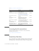
Fastener Power supply FIGURE 3-8 ▼ Replacing the Power Supply To Remove the Hard Drive 1. Perform the procedures described in “Common Procedures for Parts Replacement” on page 53. 2. Disconnect the cable from the hard drive. 3. Unsnap the catches on the latches (FIGURE 3-9) on the front of the disk drive and remove the drive and tray assembly from the chassis. Latches Hard drive Figure showing how to remove the hard disk drive.
▼ To Replace the Hard Drive 1. Unpackage the replacement hard drive and tray assembly. 2. Slide the hard drive and tray assembly into the chassis until it mates with the front of the chassis (FIGURE 3-10). Hard drive Latches FIGURE 3-10 Replacing the Hard Drive 3. Snap the catches on the latches to lock the drive and tray assembly into place in the chassis. 4. Redress the power and cable through the midwall in the chassis and reconnect the cable to the rear of the drive. 5.
▼ To Remove DIMMs Caution – This procedure requires that you handle components that are sensitive to static discharges that can cause the component to fail. To avoid this problem, ensure that you follow antistatic practices as described in “To Perform Electrostatic Discharge (ESD) Prevention Measures” on page 56. 1. Perform the procedures described in “Common Procedures for Parts Replacement” on page 53. 2. Locate the DIMM (FIGURE 4-8) that you want to replace.
TABLE 3-1 DIMM Names and Socket Numbers Socket Number DIMM Name Used in Messages* J0501 J0601 J0701 J0801 J1001 J1101 J1201 J1301 CH0/R0/D0 CH0/R0/D1 CH0/R1/D0 CH0/R1/D1 CH3/R0/D0 CH3/R0/D1 CH3/R1/D0 CH3/R1/D1 * DIMM names in messages are displayed with the full name such as MB/CMP0/CH1/R1/D1, but this table lists the DIMM namei in an abbreviated way the preceding MB/CMP0 is omitted) for clarity. 5. Grasp the top corners of the DIMM and remove it from the motherboard. 6.
6. Perform the following steps to clear the memory fault. a. Gain access to the ALOM sc> prompt. Refer to the Sun Fire T2000 Server Advanced Lights Out Management (ALOM) Guide for instructions. b.
c. Switch to the system console to view POST output. sc> console Watch the POST output for possible fault messages. The following output is an indication that POST did not detect any faults: . . . 0:0>POST Passed all devices. 0:0> 0:0>DEMON: (Diagnostics Engineering MONitor) 0:0>Select one of the following functions 0:0>POST:Return to OBP. 0:0>INFO: 0:0>POST Passed all devices. 0:0>Master set ACK for vbsc runpost command and spin...
1. Remove the PCI Express card. See “To Remove the Optional PCI Express Card” on page 58. 2. Remove the fan tray assembly and cable. See “To Remove the Fan Tray Assembly” on page 60. 3. Remove the power supply and cable. “To Remove the Power Supply” on page 61 4. Remove the hard drive and cable. See “To Remove the Hard Drive” on page 63. 5. Remove the memory DIMMs. See“To Remove DIMMs” on page 65. 6. Remove the socketed system configuration SEEPROM from the motherboard and place it on an antistatic mat.
6. Replace the memory DIMMs. “To Add or Replace DIMMs” on page 66. 7. Replace the socketed system configuration SEEPROM. The location of this SEEPROM is shown in Appendix A, “Field-Replaceable Units (FRUs)” on page 75. 8. Perform the procedures described in “Common Procedures for Finishing Up” on page 72. 9. Boot the system and run POST to verify that the system is fully operational. See “Running POST” on page 27. ▼ To Remove the Clock Battery on the Motherboard 1.
▼ To Replace the Clock Battery on the Motherboard 1. Unpackage the replacement battery. 2. Press the new battery into the motherboard (FIGURE 3-13) with the + facing upward. FIGURE 3-13 Replacing the Clock Battery on the Motherboard 3. Perform the procedures described in “Common Procedures for Finishing Up” on page 72. 4. Use the ALOM setdate command to set the day and time. Use the setdate command before you power-on the host system.
Common Procedures for Finishing Up ▼ To Replace the Top Cover 1. Place the top cover on the chassis. Set the cover down so that the cover hangs over the rear of the server by about an inch (2.5 cm). 2. Slide the cover forward until it latches into place.
▼ To Reinstall the Server Chassis in the Rack Refer to the Sun Fire T1000 System Installation Manual for installation instructions. After you have reinstalled the server chassis in the rack, reconnect all cables that you disconnected when you remover the chassis from the rack. ▼ To Apply Power to the Server 1. Reconnect the power cord to the power supply. Note – As soon as the power cord is connected, standby power is applied. Depending on the configuration of the firmware, the system might boot.
74 Sun Fire T1000 Server Service Manual • January 2006
APPENDIX A Field-Replaceable Units (FRUs) FIGURE A-1 shows the locations of the field-replaceable units (FRUs) in the Sun Fire T1000 server. TABLE A-1 lists the FRUs. TABLE A-2 lists the locations of the DIMMs. The Channel/Rank/DIMM locations.
. 5 (5) 2 (2) 4 (3) 6 (4) Motherboard (1) Disk (5) 8 7 1 FIGURE A-1 76 Field-Replaceable Units Sun Fire T1000 Server Service Manual • January 2006 3
1 TABLE A-1 Sun Fire T1000 Server FRU List Item No. CRU 1 Motherboard and chassis assembly 2 Replacement Instructions Description Location “To Remove the Motherboard and Chassis” on page 68 The motherboard and chassis are replaced as a single assembly. The motherboard is provided in different configurations to accommodate the different processor models (6 core and 8 core).
TABLE A-2 78 Location of DIMMs Connector Number Location J0501 J0601 J0701 J0810 J1001 J1101 J1201 J1301 MB/CMP0/CH0/R0/D0 MB/CMP0/CH0/R0/D1 MB/CMP0/CH0/R1/D0 MB/CMP0/CH0/R1/D1 MB/CMP0/CH3/R0/D0 MB/CMP0/CH3/R0/D1 MB/CMP0/CH3/R1/D0 MB/CMP0/CH3/R1/D1 Sun Fire T1000 Server Service Manual • January 2006