IN3264 / IN3268 HIGH RESOLUTION, VGA DISTRIBUTION AMPLIFIERS 1-IN, 4-OUT / 1-IN, 8-OUT IN3264/68 OPERATION MANUAL
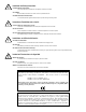
Installation and Safety Instructions For Models without a Power Switch: The socket outlet shall be installed near the equipment and shall be accessible. For all Models: No serviceable parts inside the unit. Refer service to a qualified technician. For Models with Internal or External Fuses: For continued protection against fire hazard, replace only with same type and rating of fuse.
1 Product Overview The IN3264 / IN3268 is a high-resolution dedicated VGA distribution amplifier designed to amplify and split the VGA / SVGA / XGA signal from a single computer video card to four or eight data grade displays such as data monitors, LCD projectors, presentation monitors, graphics projectors or other output devices.
2 INPUT / OUTPUT COMPATIBILITY VGA / SVGA / XGA Compatibility - The unit features 15-pin HD VGA-type connectors for input and outputs. The units will directly connect to VGA video cards and display devices using the IN8000 Series of VGA extension cables, available in a variety of lengths from 3’ to 100’. Longer lengths are available by custom order.
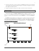
3 5. Connect the round connector on the power supply to the POWER input jack (located on the back panel of the distribution amp, immediately adjacent to Output 4.) Connect the power adapter box side of the power supply to the A/C power source. 6. Complete the installation by turning on the computer, local monitor and remote data monitors.
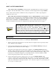
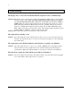
4 Opening the J2, J3 and J4 pins will remove the 75 ohm termination for each color. This setting allows users to connect a cable such as the IN9041 to the input and utilize a local monitor. Please note that if there is no local monitor and the jumper pins are set to this position, there will be unnecessary “blooming” or overdriving of the other four outputs. The input jumper pins (J8, J10 and J12) must be closed at all times.
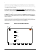
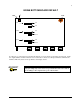
5 IN3268 BOTTOM BOARD DEFAULT LED COIL J8 J2 J9 J10 J3 J11 J12 J4 J13 To allow a loop-output, the J2, J3 and J4 pins must be open on both the top and the bottom boards. Again, the outputs will be overdriven if there is no local monitor connected to the input when the termination is disabled. This may cause serious problems to the display device.
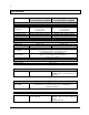
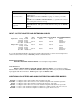
6 Specifications IN3264 VGA Distribution Amplifier IN3268 VGA Distribution Amplifier (1) 15-pin HD male connector Analog video 1.5V p-p max. 75 ohm impedance TTL RGBHV, RGBS, RGsB, RGBHVS 15 to 130 KHz 30 to 120 Hz (1) 15-pin HD male connector Analog video 1.5V p-p max.
7 Optional Accessories Power Accessories Rack Mounting Equipment IN9210 Rack Mountable Power Supply - Provides power for up to five 9VDC / 12VDC devices IN8500 Bulk Power Cable for IN9210: 18 gauge, 2-conductor power cable, bulk IN8512P Connects IN9210 to IN3264 / IN3268 - (1) 2-pin Phoenix connector & (1) round power connector, 12” long IN9080 Rack Shelf - Mounts two units side-by-side in a 1U rack space IN9088 Blank Panel - Fills space on Rack Shelf when using only one IN3264 / IN3268 INPUT / OUTPUT A
8 Troubleshooting The display device connected to the IN3264 / IN3268 output has a bad / scrambled image. Solution 1: The display device connected to the output of the distribution amplifier may not be compatible with the computer output. Many older LCD and Data Display units will not present signals at resolutions higher than 640 x 480 or 800 x 600, or horizontal scan rates above 36 KHz or 48KHz. Make sure you know what resolution mode the computer video card is set to output.
9 Warranty • INLINE warrants the equipment it manufactures to be free from defects in materials and workmanship. • If equipment fails because of such defects and INLINE is notified within two (2) years from the date of shipment, INLINE will, at its option, repair or replace the equipment at its plant, provided that the equipment has not been subjected to mechanical, electrical, or other abuse or modifications.