
User manual


Appendix D Connector Pinouts D-21
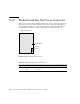
D.12 Power Supply Connector
The power supply connector pins and their corresponding descriptions are shown in
the figure and table in this section.
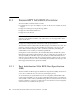
FIGURE D-12 Power Supply Connector
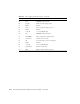
TABLE D-12 Power Supply Connector Pinouts
Pin Number Pin Name Description
PB RH1 +12V RET Main Power Return
PB RH2 +12V RET Main Power Return
PB RH3 +12V RET Main Power Return
PB RH4 +12V +12 V Power Output
PB RH5 +12V +12 V Power Output
PB RH6 +12V +12 V Power Output
A1 PS_KILL Turns off both main and standby outputs
A2 Current Share Current share signal
A3 Return Ground
A4 +3.3V SB +3.3 V Standby Output
A5 PS A0 EEPROM Address Bit 0 Input
A6 +3.3V SB +3.3 V Standby Output
B1 Return Ground
B2 Fan_Cntl Analog fan control voltage input
B3 Return Ground
B4 +3.3V SB +3.3 V Standby Output
PB RH1
PB RH6
A
B
C
D
1 2 3 4 5 6