StorageTek Virtual Tape Storage System (VTSS) for VSM5® Planning and System Assurance Guide Part Number: 96257 Revision: A
Virtual Tape Storage Subsystem (VTSS) for VSM5® Planning and System Assurance Guide
Information in this publication may be updated at any time without notice. Please direct comments about this document to the Sun Learning Services (SLS) e-mail feedback system at: slsfs@sun.com >> Or write to: Sun Learning Services Storage Technical Publications Sun Microsystems One StorageTek Drive Louisville, CO 80028-3256 USA To ensure proper handling of your comments, specify the publication name, part number, edition number, and applicable page(s) in all correspondence.
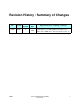
Revision History / Summary of Changes EC Doc PN SAP Revision 133687 96257 A 96257 Release Date Supported Versions / Summary of Changes New document created for FRS release of VSM5-VTSS September system (Phase 1), including 2Gb back-end FC loops, 2006 VCF3 cards, 146GB drives, detached operator panel, etc.
Contents Revision History / Summary of Changes . . . . . . . . . . . . . . . . . . . . . . . . . . . . . . . . . . . . . . . . . . . . . . . . v Notices . . . . . . . . . . . . . . . . . . . . . . . . . . . . . . . . . . . . . . . . . . . . . . . . . . . . . . . . . . . . . . . . . . . . . . . . . . . xi Warranty Notice . . . . . . . . . . . . . . . . . . . . . . . . . . . . . . . . . . . . . . . . . . . . . . . . . . . . . . . . . . . . . . . . . . xi Class 1 Laser Product Notice . . . . . . . . . . . . .
VSM5-VTSS Physical Characteristics . . . . . . . . . . . . . . . . . . . . . . . . . . . . . . . . . . . . . . . . . . . Model Numbers / Configurations / Capacities . . . . . . . . . . . . . . . . . . . . . . . . . . . . . . . . . . . . . Prerequisites for FICON Connectivity . . . . . . . . . . . . . . . . . . . . . . . . . . . . . . . . . . . . . . . . . . . Additional Prerequisites for FICON RTDs . . . . . . . . . . . . . . . . . . . . . . . . . . . . . . . . . . . . . Native FICON Attachment . . . . . .
Sample IOCP Gen for FICON Configuration . . . . . . . . . . . . . . . . . . . . . . . . . . . . . . . . . . . . . . . . . Virtual Tape Drive Mapping and Host Addressing . . . . . . . . . . . . . . . . . . . . . . . . . . . . . . . . . . . . . FRU Identifiers . . . . . . . . . . . . . . . . . . . . . . . . . . . . . . . . . . . . . . . . . . . . . . . . . . . . . . . . . . . . . . . . Array Drive Module Status Descriptions . . . . . . . . . . . . . . . . . . . . . . . . . . . . . . . . . . . . . . . . . . .
Figures Figure 1-1. System Assurance Process Flow . . . . . . . . . . . . . . . . . . . . . . . . . . . . . . . . . . . . . . . . . . . Figure 2-1. VSM Quick Tool – Tool Selection Screen . . . . . . . . . . . . . . . . . . . . . . . . . . . . . . . . . . . . . . Figure 2-2. VSM Sizer Tool . . . . . . . . . . . . . . . . . . . . . . . . . . . . . . . . . . . . . . . . . . . . . . . . . . . . . . . . . Figure 2-3. MVC Sizer Tool . . . . . . . . . . . . . . . . . . . . . . . . . . . . . . . . . . . . . . . . .
Tables Table 2-1. Configuration Planning Overview . . . . . . . . . . . . . . . . . . . . . . . . . . . . . . . . . . . . . . . . . . . . . .2-27 Table 2-2. VSM5-VTSS Environmental Requirements . . . . . . . . . . . . . . . . . . . . . . . . . . . . . . . . . . . . . .2-33 Table 2-3. VSM5-VTSS Physical Characteristics . . . . . . . . . . . . . . . . . . . . . . . . . . . . . . . . . . . . . . . . . .2-33 Table 2-4. VSM5-VTSS Model Numbers / Configurations / Capacities . . . . . . . . . . . . . . . . . . . .
Notices ■ Warranty Notice This document neither extends nor creates warranties of any nature, expressed or implied. Sun cannot accept any responsibility for your use of the information in this document, or for your use of any associated software programs. Sun assumes no responsibility for data corruption or erasure resulting from use of the information in this document, or use of software programs. You are responsible for backing up your data.
■ Hazardous Materials Handling Lead-acid battery packs and lithium-battery cards used in the VSM-VTSS are classified as hazardous materials. Sun personnel are required to comply with U.S. Department of Transportation (DOT), International Civil Aviation Organization (ICAO) and International Maritime Dangerous Goods (IMDG) Code requirements for shipping, recycling, and disposal of hazardous materials.
Australia/New Zealand – This equipment complies with EMC Framework—AS/NZS 3548: 1995. China – This equipment complies with CNS 13438. Korea – This equipment complies with Korean EMC Law. Japan: Voluntary Control Council for Interference (VCCI) – This equipment complies with VCCI (Japan) Class A (C15PR22).
■ Internal Code License Statement NOTICE INTERNAL CODE LICENSE PLEASE READ THIS NOTICE CAREFULLY BEFORE INSTALLING AND OPERATING THIS EQUIPMENT. THIS NOTICE IS A LEGAL AGREEMENT BETWEEN YOU (EITHER AN INDIVIDUAL OR ENTITY), THE END USER, AND SUN MICROSYSTEMS, INC. (‘SUN’), THE MANUFACTURER OF THE EQUIPMENT. BY OPENING THE PACKAGE AND ACCEPTING AND USING ANY UNIT OF EQUIPMENT DESCRIBED IN THIS DOCUMENT, YOU AGREE TO BECOME BOUND BY THE TERMS OF THIS AGREEMENT.
Safety / Fiber Optic / ESD Precautions The following precautions must be followed during all phases of equipment installation, operation, and servicing. Equipment users are responsible for following warnings and cautions, and for taking other appropriate steps to assure safe equipment operation. Sun assumes no liability for failure to comply with these requirements.
Strictly Comply With Caution and Warning Messages To prevent injury and equipment damage, comply with all caution and warning messages in this document. Also employ any and all other precautions which you deem necessary for safe operation of equipment in your specific operating environment. Carefully Follow Procedural Steps Always complete procedural steps in listed order. Performing steps out of order can expose you to potentially hazardous or lethal conditions.
■ Fiber Optic Component Handling Precautions To prevent damage to optical fiber cables and connectors, and to mitigate inherent hazards from laser-light emissions, always follow these general handling precautions: Protect Your Eyes Never aim the output of a laser, or of an optical fiber connected to a laser, directly into your eyes. Do not examine an optical connector on any cable that is still attached to its data transmission port, since laser light may be present in the cable.
About This Guide About This Guide ■ Product Overview The Sun StorageTek Virtual Storage Manager® (VSM®) is a disk-based virtual tape system that provides enterprise-class storage management capabilities for MVS-based systems.
■ Alert Messages Alert messages used within this document are presented as follows: Note: A note provides emphasis or additional useful detail about a topic or procedure, and can either precede or follow the information it references. CAUTION ! A caution directs urgent attention to an action or condition which could damage equipment or corrupt data or system software if the accompanying procedure is not completed or is performed incorrectly. A caution always precedes the information it references.
About This Guide ■ Where to Find Additional Information Additional information about the complete line of Sun StorageTek products and services is provided through various media, as described below. Reference Documents The VSM5 Virtual Tape Storage Subsystem (VTSS) is one of several hardware and software components that link together to create the VSM5 system.
VSM Engineering Website Extensive and detailed information about VSM, including engineering documents, Redbooks, White Papers, and standards, is available through the VSM Engineering website at http://vsm.stortek.com. Website access is restricted to Sun employees. Customer Resource Center The Sun StorageTek Customer Resource Center (CRC) website at www.support .storagetek.
About This Guide SE Support Tools SE tools, white papers, and other content for use with Sun StorageTek products, including VSM5 system equipment, are available through the SE Support Tools website at http://setools. Website access is restricted to Sun employees. Global Services Field Support Tools Resources to assist with sales and support of VSM5 system equipment and other Sun StorageTek products and services are located on the Global Services Field Support Tools website at http://sunsolve.central.sun .
1 Planning and Implementation Overview This chapter provides an overview of key participants, timelines, and activities involved in planning for and implementing a VSM5 system. Successful implementation requires regular communication and coordination between customer personnel and the Sun account team. This ongoing collaboration helps ensure that all factors critical to the implementation are identified and addressed before equipment is delivered to the site.
Planning and Implementation Overview ■ Creating Planning Teams Once a sales proposal has been accepted, the Sun customer service manager (CSM) should confer with customer-site personnel including the network administrator, data center manager, and facilities manager to identify which individuals who should be involved with implementation planning, site readiness planning, and delivery and installation planning.
Planning / Readiness / Implementation Timelines ■ Planning / Readiness / Implementation Timelines The following activity guidelines allow sufficient time for planning, readiness, and implementation tasks to be completed prior to delivery of VSM5 system equipment to a customer site. 1.
Planning and Implementation Overview • The dock manager and/or facilities manager and Sun customer service manager identify any special shipping requirements, and notify the Sun manufacturing group as needed. • The Sun sales representative completes and submits the equipment sales order, including all necessary cabling and spare parts.
Configuration Planning 2 This chapter provides an overview of configuration planning considerations and activities that are used to design a VSM5 system tailored to customer requirements, and to ensure proper implementation of the system.
Configuration Planning ■ Defining Customer Requirements Customized tools are available to assist Sun personnel with estimating customer requirements and configuring a unique VSM5 system to meet those needs. VSM Quick is a pre-sales tool package designed for use by SEs and ARs. It provides potential customers with a quick estimate of the size and scope of a VSM5 system that is tailored to their requirements. VSM Quick and other VSM-related tools are available on the SE Tools website at http://setools.
Defining Customer Requirements VSM Sizer Tool As shown in Figure 2-2, the VSM Sizer tool requests inputs on mount activity, file size, the estimated growth rate of data, and the current configuration of libraries, transports, and cartridges to determine customer requirements for a VSM5 system. Based on the results of its calculations, the tool identifies an optimum VSM5-VTSS configuration and minimum number of RTDs to meet the defined requirements.
Configuration Planning MVC Sizer Tool As shown in Figure 2-3, the MVC Sizer tool estimates the number of Multiple Volume Cartridges (MVCs) required for a VSM installation at intervals of 90 days, 180 days, 270 days, one year, two years, and three years, based on mount activity and average file size. The tool also reports estimated hours needed for daily reclaim activity, and the average number of MVCs to be added on a monthly basis after the first 90 days. Figure 2-3.
Defining Customer Requirements MVC Migration Tool As shown in Figure 2-4, the MVC Migration tool evaluates existing tape systems, tape media, channels, and data set size to estimate the number of Multiple Volume Cartridges (MVCs) required for a VSM installation at intervals of 90 days, 180 days, 270 days, one year, two years, and 3 years, and the amount of time needed to migrate data from existing manual or Nearline tape devices to the proposed VSM5 system. Figure 2-4.
Configuration Planning CDS Sizer Tool As shown in Figure 2-5, the CDS Sizer is used to determine size requirements for the HSC control data set (CDS) based on a specific VSM5 system configuration. The tool requests detailed inputs about the VSM configuration (number of LSMs, VTVs, MVCs, VTSSs, configured MVC ranges, and configured VTV ranges), then calculates the number of 4K blocks needed in the HSC database to accommodate the LSM and VSM configurations. Figure 2-5.
VTSS Configuration Planning ■ VTSS Configuration Planning A VSM5 system consists of Virtual Tape Control System (VTCS) host software, Virtual Tape Storage Subsystem (VTSS) disk hardware (tape buffers)1, real tape drives (RTDs) which attach to an Automated Cartridge System (ACS), and automated cartridge systems (ACSs), a.k.a. tape libraries. A VSM5-VTSS connects to IBM S/390-equivalent data-streaming architectures and related hardware2, and has front-end and back-end FICON connections.
Configuration Planning Model Numbers / Configurations / Capacities Table 2-4. VSM5-VTSS Model Numbers / Configurations / Capacities Base Model Number VSMB-465 VSMC-465 VSMD-465 Disk Arrays Configuration 2 x 13 + 2 + 1 (32 drives*) 3 x 13 + 2 + 1 (48 drives*) 4 x 13 + 2 + 1 (64 drives*) Data Drives* Total Capacity Capacity Feature Code Published Actual PCap PCap Effective 4:1 Effective 4:1 UtilizaCapacity# Capacity Capacity‡ tion# Base model 330GB 1250GB 1320GB 8.
VTSS Configuration Planning Prerequisites for FICON Connectivity Note: VTCS 5.1 code or later and VTSS code D01.01.00.17 or higher are required prerequisites for enabling front-end FICON connectivity between a VTSS and mainframe (host) CPU or FICON director. VTCS 6.0 code or higher and VTSS code D01.02.00.00 or higher are required prerequisites for enabling back-end FICON connectivity between a VTSS and RTDs or cluster-links (Clinks).
Configuration Planning Native FICON Attachment Native FICON attachment refers to a FICON CPU channel connected to a FICON control unit interface, which may pass through a FICON director (switch). Since the connection is all-FICON, all channels can provide the increased performance of FICON if the attached devices are capable of FICON speeds. Figure 2-6 illustrates the two attachment modes for native FICON: direct and switched.
VTSS Configuration Planning FICON Data Transfer Rates The fastest native FICON channels are rated at 200 MB/sec., but actually can achieve a maximum data rate of only 170 MB/sec. under optimum conditions. In actual practice, FICON typically operates at 40-60 MB/sec. using the 32 KB block size commonly found in tape workloads. VCF3 cards support 2 Gb link speeds; actual throughput speed is determined by many factors including block size, microcode level, etc. FICON Cabling — Short-Wave vs.
Configuration Planning VCF3 (FICON) Card Configuration Examples Note: VCF3 (FICON) cards must be installed and removed in pairs. A minimum VSM5VTSS configuration requires four VCF3 cards. Cards must be removed in the reverse order they were installed. Although there is no mechanism to restrict or support which slots VCF cards are placed in, configurations other than those shown in Figure 2-7 through Figure 2-9 will not be supported.
VTSS Configuration Planning As shown in Figure 2-8, six VCF cards provide 12 physical FICON ports, and each port supports 64 host paths (768 paths total). Cards must be installed in the slots shown (i.e., the third VCF3 card pair must be installed in slots VCF01 and VCF11).
Configuration Planning ■ Fibre Channel Cables — Available Lengths Table 2-6. Fibre Channel Cables – Available Lengths Description / Length Part Number LC-LC, 9/125, Duplex, Plenum, 10 meter (32.8 ft.), RoHS-5 10800330 LC-LC, 9/125, Duplex, Riser, 10 meter (32.8 ft.), RoHS-5 10800331 LC-LC, 9/125, Duplex, Plenum, 50 meter (164 ft.), RoHS-5 10800332 LC-LC, 9/125, Duplex, Riser, 50 meter (164 ft.), RoHS-5 10800333 LC-LC, 9/125, Duplex, Plenum, 100 meter (328 ft.
Fibre Channel Cables — Available Lengths AC Source Power Specifications and Connectors Table 2-7. VSM5-VTSS AC Source Power Specifications and Connectors AC Source Power Requirement Power Specification Power and Frequency Single-phase 170-240 VAC 30A @ 47-63 Hz Heat Dissipation 4.77 minimum kBTU/hr — 7.64 maximum kBTU/hr kVA 1.42 minimum kVA — 2.
Configuration Planning Power Requirements Table 2-9. VSM5-VTSS Power Requirements — Single AC Source Power Cable Operation Number of 16-Drive Arrays 2 3 4 AC Source Voltage In AC Source Amps (Current) In kVA kW Power Factor kBTUs Per Hour 264V 10.1A 2.7 2.5 0.95 8.6 208V 12.4A 2.6 2.5 0.98 8.6 180V 16.2A 2.9 2.9 0.99 9.9 264V 13.0A 3.4 3.3 0.95 11.1 208V 16.0A 3.3 3.3 0.98 11.1 180V 18.3A 3.3 3.3 0.99 11.1 264V 14.5A 3.8 3.6 0.95 12.4 208V 17.8A 3.7 3.
Implementation Planning 3 This chapter provides an overview of implementation planning activities and tasks, which are designed to ensure a VSM5 system is properly configured, tested, and certified according to customer requirements. Table 3-1 provides an overview of high-level activities, sub-tasks, and participants encompassed by the implementation planning process. Table 3-1.
Implementation Planning The implementation planning process is designed to identify and schedule completion of configuration, performance tuning, and performance testing activities for a VSM5-VTSS after it has been physically installed at a site. A team comprised of key customer personnel (systems administrator; network administrator; data center manager, system operator, etc.) and Sun Professional Services personnel (technical support specialist; systems engineer; customer service manager, etc.
4 Site Readiness Planning This chapter provides information about activities designed to ensure the site is equipped to accommodate the power, safety, environmental, HVAC, and data handling requirements of VSM5 system equipment. Table 4-1.Site Readiness Planning Overview Key High-Level Activities • Select site readiness team members, and define roles and responsibilities.
Site Readiness Planning ■ Site Evaluation – External Considerations Several months before delivery of VSM5 system equipment, a readiness planning team should identify and evaluate all external site factors that present existing or potential hazards, or which could adversely affect delivery, installation, or operation of the system.
Site Evaluation – Internal Considerations Transfering Equipment Point-to-Point Site conditions must be verified to ensure all VSM5 system equipment can be safely transported between the delivery dock, staging area, and data center without encountering dimensional restrictions, obstructions, or safety hazards, or exceeding rated capacities of lifting and loading equipment, flooring, or other infrastructure. Conditions that must to be verified are described below.
Site Readiness Planning Data Center Safety Safety must be a primary consideration in planning installation of VSM5 system equipment, and is reflected in such choices as where equipment will be located, the rating and capability of electrical, HVAC, and fire-prevention systems that support the operating environment, and the level of personnel training. Requirements of local authorities and insurance carriers will drive decisions as to what constitutes appropriate safety levels in a given environment.
Site Evaluation – Internal Considerations Site Power Distribution Systems The following elements of the site power distribution system should be evaluated when planning an installation of VSM5 system equipment. System Design A properly installed power distribution system is required to ensure safe operation of VSM5 system equipment. Power should be supplied from a feeder separate from one used for lighting, air conditioning, and other electrical systems.
Site Readiness Planning Equipment Grounding For safety and ESD protection, VSM5 system equipment must be properly grounded. VTSS cabinet power cables contain an insulated green/yellow grounding wire that connects the frame to the ground terminal at the AC source power outlet. A similar insulated green or green/yellow wire ground, of at least the same diameter as the phase wire, is required between the branch circuit panel and the power receptacle that attaches to each cabinet.
Site Evaluation – Internal Considerations Figure 4-2. Transient Electrical Grounding Plate Power Panel Flat Braded/ Straned Wire Plate Concrete Floor A502_047 Electrostatic Discharge Electrostatic discharge (ESD; static electricity) is caused by movement of people, furniture, and equipment. ESD can damage circuit card components, alter information on magnetic media, and cause other equipment problems.
Site Readiness Planning Environmental Requirements and Hazards VSM5 system components are sensitive to corrosion, vibration, and electrical interference in enclosed environments such as data centers. Because of this sensitivity, equipment should not be located near areas where hazardous and/or corrosive materials are manufactured, used, or stored, or in areas with above-average electrical interference or vibration levels.
Site Evaluation – Internal Considerations Floor Loading Specifications and References Table 4-3. VSM5-VTSS Floor Loading Specifications Basic Floor Load* Maximum Superimposed Floor Load # 730 kg/m2 (149 lbs./ft2) 485 kg/m2 (99 lbs./ft2) Notes: • * Load over footprint surface area (7093.7 cm2/1099.5 in2) of an unpackaged VSM5-VTSS cabinet, with a maxi- • # mum weight of 445 kg/982 lbs., i.e., a VTSS with 64 array disk drives. Assumes minimum Z+Z axis dimension of 185.3 cm/73.0 in. (i.e.
Site Readiness Planning Figure 4-3. VSM5-VTSS Cabinet Weight Distribution and Leveler Locations 92.1 (36.26) 97.40 (261) 47.11 (18.55) (2X) 75.01 (201) Z X X 109.72 (294) 84.34 (226) Z 6.29 (2.725) (2X) 6.29 (2.725) (2X) 77.1 (30.35) 14.98 (5.90) (2X) 77.59 (30.55) (2X) A504 026 Raised-Floor Lateral Stability Ratings In areas of high earthquake activity, the lateral stability of raised floors must be considered.
Site Evaluation – Internal Considerations Raised-Floor Pedestal Ratings Raised floor pedestals must be able to resist an axial load of 2268 kg (5000 lbs.). Where floor panels are cut to provide service access, additional pedestals may be required to maintain the loading capacity of the floor panel. Physical Space Requirements Floor space and layout requirements can differ for each VSM5 system configuration. Figure 4-4 shows dimensions and recommended service clearances for a VSM5-VTSS cabinet.
Site Readiness Planning This page is intentionally blank.
Specifications and Additional Information A This appendix provides specifications and additional information for the VSM5-VTSS.
Specifications and Additional Information ■ Motherboard and FRU Interconnections – Side 0 Figure A-1.
Motherboard and FRU Interconnections – Side 1 ■ Motherboard and FRU Interconnections – Side 1 Figure A-2.
Specifications and Additional Information ■ Power Safety Grounding Diagram – Side 0 Figure A-3. VSM5-VTSS Power Safety Grounding Diagram – Side 0 Not a Controlled Connection for Safety Purposes 3 Power Strip 0 Array PS-0 #16 Pigtail 6.
Power Safety Grounding Diagram – Side 1 ■ Power Safety Grounding Diagram – Side 1 Figure A-4. VSM5-VTSS Power Safety Grounding Diagram – Side 1 Not a Controlled Connection for Safety Purposes 3 Power Strip 1 Array PS-1 #16 Pigtail 6.3A(X2) 6 7 6-32 Array PS-3 #16 Pigtail Frame 3 6.3A(X2) 9 6-32 Array PS-5 #16 Pigtail Frame 6.
Specifications and Additional Information ■ Power System Diagram Figure A-5.
Data Paths and Interfaces ■ Data Paths and Interfaces Figure A-6.
Specifications and Additional Information ■ Fiber Optic Cable Specifications Table A-1. Fiber Optic Cable Specifications Optical Performance Specification Attenuation 1.0 dB/km @ 1300 nm Bandwidth 500 MHz/km @ ≤2 km Handling Characteristics Specification Pulling Strength 27.2 kg (60 lbs.) Crush Resistance 650 Newtons/cm (371 ft-lbs/in2) Minimum Bend Radius 96 mm (3.74 in.) Cable Weight 59.7 kg/100 m (401 lbs./1000 ft.
Sample IOCP Gen for FICON Configuration ■ Sample IOCP Gen for FICON Configuration Figure A-7. Sample IOCP Gen for FICON Configuration >> NOTE: The example below shows an IOCP gen for a single MVS host connected to a VSM5 through FICON directors.
Specifications and Additional Information ■ Virtual Tape Drive Mapping and Host Addressing A VSM5-VTSS can be configured with up to 256 virtual tape drives (VTDs). During VTSS installation, all 256 available VTDs are mapped as shown in Table A-3 below. Mapping of all available VTDs is required by VTSS microcode, and applies whether the VTDs are ultimately defined or undefined. Table A-3.
FRU Identifiers ■ FRU Identifiers Table A-4. VSM5-VTSS FRU Identifiers Physical Location FRU Common Name FRU Silkscreen FRU Number (Hex) FRU Number (Decimal) FRU Location ID (Unit.Tray.Slot) 78 CU.0.PDU0 Power Distribution Units CU Front Tray 0 Power Distribution Unit 0 PDU2-O 4E CU Front Tray 0 Power Distribution Unit 1 PDU2-1 4F 79 CU.0.PDU1 Inside PDU0 PDU0 Internal Fan FAN 0 3C1 961 CU.0.FAN0 Inside PDU1 PDU1 Internal Fan FAN 1 3C2 962 CU.0.FAN0 4C 76 CU.3.
Specifications and Additional Information Table A-4. VSM5-VTSS FRU Identifiers (Continued) Physical Location FRU Common Name FRU Silkscreen CU Rear CU Motherboard ACMB CU Front Tray1 VCF3 Card 0 CU Front Tray1 FRU Number (Hex) FRU Number (Decimal) FRU Location ID (Unit.Tray.Slot) 1C 28 CU.1.ACMB VCF00 5 5 CU.1.VCF00 VCF3 Card 1 VCF01 6 6 CU.1.VCF01 CU Front Tray1 VCF3 Card 2 VCF02 8 8 CU.1.VCF02 CU Front Tray1 VCF3 Card 3 VCF03 9 9 CU.1.
FRU Identifiers Table A-4. VSM5-VTSS FRU Identifiers (Continued) Physical Location FRU Common Name FRU Silkscreen CU Rear Tray 1 LPS0 Fan 0 FAN-0 CU Rear Tray 1 LPS0 Fan 1 CU Rear Tray 1 FRU Number (Hex) FRU Number (Decimal) FRU Location ID (Unit.Tray.Slot) 3BD 957 CU.1.FAN0 FAN-1 3BE 958 CU.1.FAN1 LPS1 Fan 2 FAN-2 3BF 959 CU.1.FAN2 CU Rear Tray 1 LPS1 Fan 3 FAN-3 3C0 960 CU.1.FAN3 CU Rear Tray 2 Card Cage Impeller 0 IMP0 38A 906 CU.2.
Specifications and Additional Information Table A-4. VSM5-VTSS FRU Identifiers (Continued) Physical Location FRU Common Name FRU Silkscreen FRU Number (Hex) FRU Number (Decimal) FRU Location ID (Unit.Tray.Slot) Physical Array Disk Drive Tray 2 DA Rear Physical Drive Tray 2 (Logical Tray DA0.2) Array Drive Module 0 DRV0 A0 160 DA.2.DRV0 Array Drive Module 1 DRV1 A1 161 DA.2.DRV1 Array Drive Module 2 DRV2 A2 162 DA.2.DRV2 Array Drive Module 3 DRV3 A3 163 DA.2.
FRU Identifiers Table A-4. VSM5-VTSS FRU Identifiers (Continued) Physical Location FRU Common Name FRU Silkscreen FRU Number (Hex) FRU Number (Decimal) FRU Location ID (Unit.Tray.Slot) Physical Array Disk Drive Tray 5 DA Rear Physical Drive Tray 5 (Logical Tray DC0.1) Array Drive Module 0 DRV0 FA 250 DA.5.DRV0 Array Drive Module 1 DRV1 FB 251 DA.5.DRV1 Array Drive Module 2 DRV2 FC 252 DA.5.DRV2 Array Drive Module 3 DRV3 FD 253 DA.5.DRV3 Array Drive Module 4 DRV4 FE 254 DA.5.
Specifications and Additional Information ■ Array Drive Module Status Descriptions The Disk Drive / Array Status screen displays the status of each VTSS array drive as a two-character code. The first character defines the partition a specific drive is associated with; the second characther defines the current state of the drive. For example, a status of ‘P.A’ indicates that a drive is in production partition (‘P’) and active (‘A’).
Array Drive Module Status Descriptions Table A-5. Array Drive Module Status Descriptions Drive Module Status Status Code Meaning/Description Production Partition Production: Active P.A (PA) Drive is active. Production: Broken P.B (PB) Drive is inactive and marked as broken. After its data is moved to a spare, broken drive is removed from Production partition and put in ‘Unavailable: Broken’ (U.B) state. Production: Copy P.C (PC) Drive is receiving data from drain of Production drive.
Specifications and Additional Information This page is intentionally blank.
FICON Channel Extension Guidelines B This appendix provides information about FICON channel extensions for the VSM system.
FICON Channel Extension Guidelines ■ Definition of Terms The following terms are used in this appendix: • Front-end – any equipment between a host and a VTSS • Back-end – any equipment between a VTSS and RTD • Channel extension – a configuration of equipment that exceeds the maximum distance allowed by native FICON protocol, implemented by adding a pair of channel extenders.
General Channel Extension Considerations ■ General Channel Extension Considerations Understand Channel Extension Performance Limitations Channel extension usually involves using a WAN (wide-area network), which possibly operates at slower-than-FICON speeds. At the very least, the addition of channel extenders will cause additional overhead, and will slow down tape I/O processing.
FICON Channel Extension Guidelines ■ FICON Topologies See “Placement of Extension Equipment” below to determine proper placement of extension equipment for the following FICON topologies: 1. Host-to-VTSS (front-end link to VTDs) a. direct-attach connection b. single FICON director/switch connection c. cascaded directors/switches connection 2. VTSS-to-RTD (back-end link to RTDs) a. direct-attach connection b. single FICON director/switch connection c. cascaded directors/switches connection 3.
FICON Channel Extension – Sample Configurations ■ FICON Channel Extension – Sample Configurations Figure B-1. Host-to-VTSS Channel Extension – Direct Attachment z/OS Host VTSS Tape Silo with RTDs Channel Extender A502_048 Figure B-2. Host-to-VTSS Channel Extension – Behind Single FICON Switch / Director z/OS Host VTSS FICON Director/Switch Tape Silo with RTDs Channel Extender A502_049 Figure B-3.
FICON Channel Extension Guidelines Figure B-4. VTSS-to-RTD Channel Extension – Direct Attachment z/OS Host Tape Silo with RTDs VTSS Channel Extender A502_051 Figure B-5.
McData/CNT Channel Extension Interoperability Figure B-6.
FICON Channel Extension Guidelines The FICON directors on the supported list provide a port configuration option for link speed. The VSM port runs in auto-speed mode (currently unconfigurable). The recommendation is to set all FICON director ports attached to extension equipment to a fixed speed, and to set the attached extension ports to a fixed speed, as follows: • Set the FICON director port to ‘1Gbps-ONLY’ for attachment to the USD-X channel extender.
Cisco Systems Channel Extension Interoperability ■ Cisco Systems Channel Extension Interoperability The following interoperability and configuration information and guidelines apply when using Cisco Systems channel extension equipment with a VSM-VTSS. Note: This qualification is for distances up to 200km without any performance penalty. Cisco is planning a performance improvement beyond the current 200km limit, which will be tested by Sun once that code level is delivered.
FICON Channel Extension Guidelines This page is intentionally blank.
Glossary A AC. Alternating current. Current in which the direction is reversed, or alternated, 60 times per second (50 times per second in some countries). Contrast with direct current. acceptance test. A formal test done by a system enduser to determine if a system works according to specifications and should be accepted. access density. A measure of I/O activity; the number of I/O operations per gigabyte of functional capacity per second. access privileges.
asynchronous. Not synchronized; not occurring at regular, predetermined intervals. Asynchronous transmissions send one data character at a time, at irregular intervals, rather than in one steady stream; a start bit and a stop bit notify the receiver when the transmission begins and ends. Contrast with synchronous. ATA. Advanced Technology Attachment. Official name for the disk drive interface standard commonly known as Integrated Drive Electronics (IDE). ATM. Asynchronous transfer mode.
CD-ROM. Compact Disc Read-Only Memory. An optical disc that may contain computer data, audio data, graphics, and other information, and is interchangeable between different types of computers. Storage capacity is typically about 680 MB per disc. CDS. Control data set. An HSC database containing all configuration and volume information, used by host software to control functions of automated libraries. CEI. Configured end item. CFE. Composite Failure Event.
control unit address. The base channel address to which a control unit can respond. conversion. A process that changes the basic capability of a unit in a system and may be a disruptive, requiring a customer to turn over use of the unit to a CSE. Conversions may require special tools and higher-level skills of a technical specialist. Contrast with upgrade. count-key data (CKD). A recording format that writes variable-length records. Contrast with fixed-block architecture. CPAT.
digital. Information stored in binary form that a computer recognizes. For computing use, text, graphics, and sound are stored as digital bits represented by a 0 or 1. Contrast with analog. dimmed text. Dimmed or grayed-out text that appears on a GUI menu and indicates an option is unavailable because the system is not in the mode to use that function, or because software for that function is not installed. Available options are typically displayed in undimmed black text. Dynamic Configuration.
environmental stress screening (ESS). A method of causing weak components in a machine to fail by applying environmental stresses much greater than normal product environmental specifications, including temperature extremes, temperature shock, and vibration. F EPE. Early/External Product Evaluation fabric. (1) In Fibre Channel (FC), a structure that allows addressing of ports on a FC network to be done independently of the physical location or address of a target port.
Fibre Channel (FC). An ANSI-standard serial interface used to provide high-speed data transfers between workstations, servers, desktop computers, peripherals and, more recently, as a channel for attachment of storage devices. FC allows concurrent communication between connected elements. FC topologies include Fibre Channel-Arbitrated Loop (FC-AL), point-to-point, and switched fabric. ume image as known to a VTSS. FICON. FIbre CONnection.
H technology with ISO. half-duplex. A communications channel that transmits data in either direction, but only one direction at a time. Contrast with full-duplex. handshake. (1) A signal exchanged between two software components that uses characters inserted into a data stream to indicate when to start or stop sending data. (2) A voltage or pulse signal exchanged between two hardware components to establish a valid connection between two computers. HBA. Host bus adapter.
J logical array. A grouping of devices into an array independent of physical device locations. jack. A connector into which a plug is inserted. logical block address (LBA). A four-byte number used to identify a logical block on a SCSI drive. The address range is 0 to n, where n equals the number of blocks on a drive. JBOD. Just a Bunch of Disks. A term used to describe a data storage cabinet that contains only disk storage devices, without an internal control unit.
mean time between failures (MTBF). A figure that gives an estimate of equipment reliability. The higher the MTBF, the longer a piece of equipment should last. For example, if MTBF is 10,000 hours, the equipment should run, on average, for 10,000 hours before failing. mean time to repair (MTTR). Average time from the beginning of troubleshooting activities (when a CSE starts work on a unit) until a subsystem (or part of it) is returned to full functionality and total customer control.
P packet. A unit of data formatted for transmission on a network. Each packet has a header containing its source and destination, a block of data content, and an errorchecking code. The data packets for a specific message may take different routes to a destination, and the packets are reassembled on arrival. PAD. Packet assembly/disassembly. See packet. PAL. Programmable Array Logic. parallel. Side by side.
relative humidity. The amount of moisture in the air, as compared with the maximum amount of humidity that the air could contain at the same temperature; expressed as a percentage. relocation. The process of physically moving VTSS units within a same site or immediate area without the use of packing materials. Contrast with deinstallation. remote customer service engineer (RCSE).
support facility. VTSS functionality provided by ISP cards and support facility software that enables human interface with a VTSS for monitoring, communication, and testing. synchronous. (1) Synchronized by a common timing signal. (2) Occurring with a regular or predictable time relationship. Synchronous transmissions send strings of data characters at regular intervals without the need for start and stop bits required for asynchronous transmissions, making them faster than asynchronous transmissions.
VTCS. Virtual Tape Control System. In VSM, primary host software that controls activity and coordinates operations between the host operating system and the VTSSs, VTVs, RTDs, and MVCs, as represented in front-end tape drives or libraries and back-end disk arrays. VTCS software operates in the same address space as the HSC, and communicates closely with it. VTD. Virtual Tape Drive. A transport in a VTSS that emulates a physical 3490E tape drive to a MVS system.
Forms and Reference Notes D This appendix provides electronic forms and worksheets for recording information related to pre-installation planning tasks for a VSM5-VTSS at a specific location, including: • • • • • • • Customer site details Customer personnel contact details Sun and QSP1 personnel contact details System software reference information System hardware reference information Planning task-completion worksheets Planning and system assurance reference notes Note: Forms in this appendix are desi
Account Information > [electronic form] < Account (Company) Name Site Number Street Address City / State / Province / Region Zip or Postal Code / Country Other Account Details Host System Configuration Information > [electronic form] < Host Name Host Address Other Host Configuration Details VTSS Configuration Information > [electronic form] < VTSS Name License Key Time Zone Setting Other VTSS Configuration Details Sun Confidential: Internal Only
Customer Personnel Contacts > [electronic form] < Account ______________________________________ Data Center Manager (name) Phone Numbers (office / cell) E-Mail Address(es) Other Contact Information Network Administrator (name) Phone Numbers (office / cell) E-Mail Address(es) Other Contact Information Site Engineer (name) Phone Numbers (office / cell) E-Mail Address(es) Other Contact Information Facilities Manager (name) Phone Numbers (office / cell) E-Mail Address(es) Other Contact Information Data Center
Sun StorageTek / QSP Personnel Contacts > [electronic form] < Account ______________________________________ Account Representative (name) Phone Numbers (office / cell) E-Mail Address(es) Other Contact Information System Engineer (name) Phone Numbers (office / cell) E-Mail Address(es) Other Contact Information System Support Specialist (name) Phone Numbers (office / cell) E-Mail Address(es) Other Contact Information Technical Support Specialist (name) Phone Numbers (office / cell) E-Mail Address(es) Other
Planning Worksheet 1 of 5 > [electronic form] < Account __________________________ Completed By ____________________ Date ___________ Site Readiness Planning Factors Information to Note / Comments 1A. Installation teams defined? 1A. 1B. Installation schedule created? 1B. 1C. HVAC requirements compliance verified? 1C. 1D. Power requirements compliance verified? 1D. 1E. Flooring requirements compliance verified? 1E. 1F. Future expansion considered? 1F. 1G. Floor plans completed? 1G. 1H.
Planning Worksheet 2 of 5 > [electronic form] < Account __________________________ Completed By ____________________ Date ___________ Delivery and Handling Factors Information to Note / Comments 2A. Does the customer have a delivery dock? If NO, where 2A. will the VTSS cabinet(s) be delivered? 2B. Are there street or alley limitations that will hinder delivery of the VTSS cabinet(s)? 2B. 2C. Is the delivery dock available only during specific hours? If YES, what are the hours of availability? 2C. 2D.
Planning Worksheet 3 of 5 > [electronic form] < Account __________________________ Completed By ____________________ Date ___________ Safety and Fire Prevention Factors 3A. Have all safety and fire-prevention codes and regulations been reviewed for this VTSS installation? Information to Note / Comments 3A. Hardware / Software Procurement Factors Information to Note / Comments 3B. Has the VTSS configuration, including all features and optional upgrades, been defined? 3B. 3C.
Planning Worksheet 4 of 5 > [electronic form] < Account __________________________ Completed By ____________________ Date ___________ Physical Placement Factors Information to Note / Comments 4A. Does the installation area provide sufficient floor space 4A. for all the hardware that comprises this VSM solution? 4B. Does the installation area provide adequate lighting and clearances for safety, operation, and maintenance of all 4B. the hardware that comprises this VSM solution? 4C.
Planning Worksheet 5 of 5 > [electronic form] < Account __________________________ Completed By ____________________ Date ___________ AC Power Factors Information to Note / Comments 5A. Does the installation site have capability for grounding the VTSS cabinet(s)? 5A. 5B. Is the installation site close enough to source power connectors / outlets to accommodate the power cord lengths ordered for the VTSS cabinet(s)? 5B. 5C. Are power cable routing paths readily accessible to fa5C.
Software Information > [electronic form] < Account ______________________________________ Use this electronic form to record key information (product names, versions, release levels, serial numbers, etc.) for all software1 used with this VSM solution configuration, as a quick reference when reporting problems, validating service entitlements, etc. 1. Including: VSM application software (VTCS, NCS, HSC), library software (ACSLS, Library Station), and MVS host system software.
Hardware Information – Tape Devices > [electronic form] < Account ______________________________________ Use this electronic form to record key information (product names, model numbers, serial numbers, etc.) for all tape device hardware1 used with this VSM solution configuration, as a quick reference when reporting problems, validating service entitlements, etc. NOTE: To ensure accurate notations, identify tape devices by product name and type (e.g., 9940B tape drive, SL8500 tape library, etc.
Hardware Information – Switches / Routers > [electronic form] < Account ______________________________________ Use this electronic form to record key information (product names, model numbers, serial numbers, etc.) for all external switches, routers, or other hardware used with this VSM solution configuration, as a quick reference when reporting problems, validating service entitlements, etc.
Hardware Information – SDP and Modem Devices > [electronic form] < Account ______________________________________ Use this electronic form to record key information (product names, model numbers, serial numbers, etc.) for all Service Delivery Platform (SDP) and remote service modem hardware used with this VSM solution configuration, as a quick reference when reporting problems, validating service entitlements, etc.
Notes / Additional Information > [electronic form] < Account ______________________________________ Sun Confidential: Internal Only
Notes / Additional Information > [electronic form] < Account ______________________________________ Sun Confidential: Internal Only
Notes / Additional Information > [electronic form] < Account ______________________________________ Sun Confidential: Internal Only
Notes / Additional Information > [electronic form] < Account ______________________________________ Sun Confidential: Internal Only
Notes / Additional Information > [electronic form] < Account ______________________________________ Sun Confidential: Internal Only
Sun Microsystems, Inc. 4150 Network Circle, Santa Clara, CA 95054 USA Phone 1-650-960-1300 or 1-800-555-9SUN Web sun.