STP2002QFP Revision 1.0–April 1996 STP2002QFP Fast Ethernet, Parallel Port, SCSI (FEPS) USER’S GUIDE OVERVIEW 1 1.1 Introduction The STP2002QFP FEPS (Fast Ethernet®, Parallel, SCSI) is an ASIC that provides integrated high-performance SCSI, 10/100 Base-T Ethernet, and a Centronics compatible parallel port. 1.
STP2002QFP Fast Ethernet, Parallel Port, SCSI (FEPS) - STP2002QFP terface (CEI) for slave and DMA transfers with the SBus (via SBA). The SBA provides buffering and bus conversion between the SBus and the channel engine interface. Interrupts from the channel engine go directly to the SBus. The SBA contains no software-accessible registers. The channel engine interface provides a common interface to the three channel engines thus reducing verification time.
Fast Ethernet, Parallel Port, SCSI (FEPS) - STP2002QFP STP2002QFP 109 rev10h, ISO/IEC 8802-3, IEEE 802.3u 100 Base-T, IEEE 1149.1 ( JTAG), Centronics-protocol-compatible parallel port, and the Sun4u system architecture.
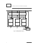
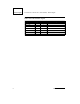
STP2002QFP Fast Ethernet, Parallel Port, SCSI (FEPS) - STP2002QFP SBus SBA Channel Engine Interface ENET_IRQ SCSI_IRQ PP_IRQ SCSI DVMA ENET DMA PP DMA FAS366 BigMac PP Core SCSI_Channel SCSI Bus ENET_Channel PP_Channel MII Interface Boot PROM Parallel Port Figure 1.
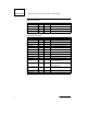
Fast Ethernet, Parallel Port, SCSI (FEPS) - STP2002QFP STP2002QFP 1.6 Pin Descriptions The signal pins are grouped by function in the following tables.
STP2002QFP Fast Ethernet, Parallel Port, SCSI (FEPS) - STP2002QFP Table 2: SCSI Signals Signal Name Type Pin Count Description SCSI_XTAL2 O 1 SCSI crystal output SCSI_XTAL1 I 1 SCSI crystal input POD I 1 SCSI power detect Total SCSI 30 Table 3: Ethernet Signals Signal Name Pin Count Description ENET_TX_CLK I 1 Ethernet transmit clock input ENET_TXD[3:0] O 4 Ethernet transmit data ENET_TX_EN O 1 Ethernet transmit enable ENET_COL I 1 Ethernet transmit collision detected
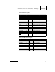
Fast Ethernet, Parallel Port, SCSI (FEPS) - STP2002QFP STP2002QFP Table 4: Parallel Port Signals Type Pin Count PP_DATA[7:0] Signal Name I/O 8 Parallel port data bus Description PP_STB I/O 1 Parallel port data strobe PP_BSY I/O 1 Parallel port busy PP_ACK I/O 1 Parallel port acknowledge PP_PE I 1 Parallel port paper error PP_SLCT I 1 Parallel port select PP_ERROR I 1 Parallel port error PP_INIT O 1 Parallel port initialize/ALE high address byte PP_SLCT_IN O 1 Paralle
STP2002QFP Fast Ethernet, Parallel Port, SCSI (FEPS) - STP2002QFP Table 6: Power/Ground/Other Signals Signal Name VDD_CORE 8 Type Pin Count Description 4 VSS_CORE 4 VDD 21 VSS 52 Reserved 1 MODE 1 Total 83 Mode select (stand alone/chipset) Sun Microelectronics
Fast Ethernet, Parallel Port, SCSI (FEPS) - STP2002QFP STP2002QFP SBUS ADAPTER 2 2.1 Introduction The SBus Adapter (SBA) is the layer between the Channel Engine Interface (CEI) and the SBus. It provides one master port on the SBus side to funnel three DMA channel engines (CE) onto the SBus, and one slave port for SBus accesses to the CEs. The SBA can be viewed as a block of data path and flow control between SBus and channel engine interface. 2.2 SBus Capabilities 2.2.
STP2002QFP Fast Ethernet, Parallel Port, SCSI (FEPS) - STP2002QFP slave accesses from SBus. The physical address is decoded to select a target CE to respond to the access. A physical address that cannot be resolved to the selection of any channel engine will cause SBus Adapter to return Error Ack. The access size is decoded to Error Ack 64-bit transfer mode or burst transfer that is not supported by FEPS. 2.3 Theory of Operation 2.3.
Fast Ethernet, Parallel Port, SCSI (FEPS) - STP2002QFP STP2002QFP machine. After this the arbiter is available to arbitrate and grant the next request on the CEI provided that there is a DMA write or read buffer still available. The master port state machine wakes up and request the SBus whenever there is a request in the queue. When SBus is granted, the master port state machine asserted BG to the corresponding CE and pass the read data over to the CEI bus. 2.3.
STP2002QFP Fast Ethernet, Parallel Port, SCSI (FEPS) - STP2002QFP SCSI CHANNEL 3 3.1 Introduction The SCSI channel consists of SCSI DVMA (also referred to as SCSI channel engine) and FAS366, a “Fast and Wide” SCSI controller core. The SCSI DVMA provides two 64-byte buffers used to transfer data to/from the FAS366. The FAS366 supplies a 16-bit SCSI data path and a throughput of 20 MB/sec. All programmed I/O access to the FAS366 is driven by the SCSI DVMA.
Fast Ethernet, Parallel Port, SCSI (FEPS) - STP2002QFP STP2002QFP - 5-MHz synchronous (normal SCSI) - 6-MHz asynchronous • REQ/ACK programmable assertion/deassertion control • Power-on connect/disconnect to SCSI bus (hot plugging) • Target block transfer sequence • Initiator block transfer sequence • Bus idle timer • Reduced SCSI bus overhead • On-chip, single-ended SCSI drivers (48 mA) • Target and initiator modes • 16-bit recommand counter • Differential mode support For more information on FAS366, refe
STP2002QFP Fast Ethernet, Parallel Port, SCSI (FEPS) - STP2002QFP PARALLEL PORT CHANNEL 4 4.1 Introduction The parallel port interface implementation of FEPS is almost identical to the one on the STP2000 Master I/O controller chip to leverage the existing device driver. The only difference is that the DIR bit has to be set during a memory clear operation. It allows the CPU to send data to the standard Centronics printer in both programmed I/O and DMA modes.
Fast Ethernet, Parallel Port, SCSI (FEPS) - STP2002QFP STP2002QFP None of these conditions will cause draining if P_ERR_PEND = 1, indicating that a memory error has occurred. If condition 4 or 5 occurs when the P_ERR_PEND bit is 1, the P_FIFO will be invalidated and all dirty data will be discarded. 4.3 Bidirectional Parallel Port Interface The parallel port can operate unidirectionally or bidirectionally in either a programmed I/O mode or in a DMA mode.
STP2002QFP Fast Ethernet, Parallel Port, SCSI (FEPS) - STP2002QFP fined as three SBus clocks. That is, the minimum data strobe width is three SBus clocks. The following table shows the nominal range of programmability for different SBus clock speeds.
STP2002QFP Fast Ethernet, Parallel Port, SCSI (FEPS) - STP2002QFP Table 7: SBus Clock DSS DSW 16.67 MHz 0–7.62 µs 180.0 ns–7.62 µs 20 MHz 0–6.35 µs 150.0 ns–6.3 µs 25 MHz 0–5.08 µs 120.0 ns–5.08 µs The desired handshake protocol can be selected using the ACK_OP (acknowledge operation) and BUSY_OP (busy operation) bits of the operations configuration register (OCR). The function of these bits is defined as follows: ACK_OP 1 = Handshake complete with receipt of P_ACK (PP_ACK).
STP2002QFP Fast Ethernet, Parallel Port, SCSI (FEPS) - STP2002QFP when the peripheral device cannot receive another byte of data. P_BSY (PP_BSY) is sampled before data strobe becomes active and after data strobe becomes inactive, to ensure that a data transfer is not attempted while the device is busy. It is this mode, which provides the fastest transfer of data over the interface, the fastest cycle time is six SBus clocks per byte.
STP2002QFP Fast Ethernet, Parallel Port, SCSI (FEPS) - STP2002QFP P_DATA (O) P_D_STRB 1 DSS 2 DSW 5 (O) 3 P_ACK (I) 4 1. Data setup as defined in the hardware configuration register. 2. Data strobe width as defined in the hardware configuration register. 3. Acknowledge is required for each byte transferred. 4. When P_BSY is active, it gates further data transfers. 5.
STP2002QFP Fast Ethernet, Parallel Port, SCSI (FEPS) - STP2002QFP 4.3.1.2 Bidirectional Operation Bidirectional data transfer over the parallel port can be accomplished by the use of either of two master/slave protocols. The “master write” protocol or the “master read/write” protocol.
Fast Ethernet, Parallel Port, SCSI (FEPS) - STP2002QFP STP2002QFP Table 9: Signal P_D_STRB (PP_STB) I/O DIR_Pin O P_DS_DIR (PP_DSDIR) State 1 P_ACK (PP_ACK) I P_ACK_DIR (PP_ACKDIR) 0 P_BSY (PP_BSY) I P_BSY_DIR (PP_BSYDIR) 0 P_DATA (PP_DATA) O P_D_DIR (PP_DDIR) 1 When DIR is set to 1, the pins configured as bidirectional change direction and their corresponding direction control pins are set accordingly.
STP2002QFP Fast Ethernet, Parallel Port, SCSI (FEPS) - STP2002QFP These two bits allow selection of one of four possible handshake protocols. The following table summarizes the protocol definitions for transfers to the parallel port from the peripheral device. For all protocol selections, P_BSY (PP_BSY) will become active if one of the following conditions occur: The P_DMA_ON bit is reset indicating DMA cannot proceed; or the P_FIFO is unable to accept more data.
Fast Ethernet, Parallel Port, SCSI (FEPS) - STP2002QFP STP2002QFP as required to gate further transfers but not as a handshake signal. The operation of the interface as defined assumes the bidirectional sense of each signal has been configured as follows: DIR=1, DS_DSEL=1, ACK_DSEL=1, BUSY_DSEL=1. The configuration of P_BSY (PP_BSY) as an output is suggested to avoid potential data loss. Reference the data transfer diagram in Figure 6. P_DATA (I) P_D_STRB 1 DSS (I) 2 DSW P_ACK (O) 3 1.
STP2002QFP Fast Ethernet, Parallel Port, SCSI (FEPS) - STP2002QFP P_DATA (I) P_D_STRB (I) Logic 0 P_ACK (O) 1 DSS 1. P_BSY hold time after data strobe (DSS - hardware configuration register) 2. All signal polarities shown are at the HIOD pins. Polarities on the interface cable should be inverted (except P_DATA). Figure 7. 4.3.1.3.4 Handshake with ACK and BUSY: (BUSY_OP=1, ACK_OP=1) Both P_ACK (PP_ACK) and P_BSY (PP_BSY) are generated in response to a data strobe.
Fast Ethernet, Parallel Port, SCSI (FEPS) - STP2002QFP STP2002QFP 4.3.1.4 Master Read/Write Protocol (Xerox Mode) This section describes the parallel port operation while master read cycles are performed. Operation while master write cycles are performed is the same as is described in the “Unidirectional Operation (Transfers to the Peripheral Device)” section on page 15.
STP2002QFP Fast Ethernet, Parallel Port, SCSI (FEPS) - STP2002QFP eration for transfers to and from the peripheral device. 4.3.2.1 PIO on Transfers to the Peripheral Device For transfers to the peripheral device, all signals are under the control of software. There is no hardware assist other than interrupt generation. 4.3.2.2 PIO on Transfers From the Peripheral Device The two modes of bidirectional operation previously discussed are supported with hardware-assisted data latching.
Fast Ethernet, Parallel Port, SCSI (FEPS) - STP2002QFP STP2002QFP 4.4 Differences from STP2000 (MACIO) Parallel Port • PP_INIT and PP_AFXN have extra functions: high and low address latch clocks • EPROM address is given by parallel port data bus • DIR bit in the TCR register must be set during memory clear operation 4.5 Test Support The TST_CSR provides a way for the user to test the DMA engine. The test consists of moving one block data of the size of a read burst from the host memory into the FIFO.
STP2002QFP Fast Ethernet, Parallel Port, SCSI (FEPS) - STP2002QFP ETHERNET CHANNEL 5 5.1 Introduction The Ethernet channel is a dual-channel intelligent DMA controller on the system side, and an IEEE 802.3 Media Access Control (MAC) on the network side. It is designed as a high-performance full-duplex device, allowing for simultaneous transfers of data from/to host memory to/from the “wire.
Fast Ethernet, Parallel Port, SCSI (FEPS) - STP2002QFP STP2002QFP For TCP packets, hardware support is provided for TCP checksum computation. On transmit, it is assumed that the entire packet is loaded into the local FIFO before its transmission begins. The checksum is computed on-the-fly while the packet is being transferred from the host memory into the local FIFO. The checksum result is then stuffed into the appropriate field in the packet, and the transmission of the frame begins.
STP2002QFP Fast Ethernet, Parallel Port, SCSI (FEPS) - STP2002QFP • Transceiver interface (XIF) - Implements the MII interface protocol (excluding the management interface) - Performs the nibble-to-byte and byte-to-nibble conversion between the protocol engine and the MII 30 Sun Microelectronics
Fast Ethernet, Parallel Port, SCSI (FEPS) - STP2002QFP STP2002QFP 5.2.2.2 Management Interface Function (MIF) The management interface block implements the management portion of the MII interface to an external transceiver, as defined in the IEEE 802.3 MII specification. It allows the host to program and collect status information from two external transceivers connected to the MII. The MIF supports three modes of operation.
STP2002QFP Fast Ethernet, Parallel Port, SCSI (FEPS) - STP2002QFP ation can only be used when the MIF is in the frame mode. 5.2.2.3 Ethernet Transmit Block (ETX) The Ethernet transmit block provides the DMA engine for transferring frames from the host memory to the BigMAC. It contains a local buffer of 2K bytes for rate adaptation between the available bandwidth on the SBus and on the network. 5.2.2.
Fast Ethernet, Parallel Port, SCSI (FEPS) - STP2002QFP STP2002QFP Receive Clock Domain This clock is used to drive the receive protocol engine in the BigMAC core. It is sourced by the MII and has the operating frequency of 2.5/25 MHz 100 ppm. The 2.5/25 MHz version of this clock (RX_NCLK) is used for strobing in the packet data from the MII and for nibble-to-byte conversion of the incoming data stream. The 1.25/12.
STP2002QFP Fast Ethernet, Parallel Port, SCSI (FEPS) - STP2002QFP The size of the descriptor ring is programmable, and it can be varied in the range of 16–256 in increments of 16 descriptors: 16, 32, 48, ..., 240, 256. 5.2.6 Receive Free Buffer Descriptor Ring For receive operation, the device driver requests a pool of free buffers from the operating system. The buffers are posted to the hardware by allocating a descriptor for each buffer.
Fast Ethernet, Parallel Port, SCSI (FEPS) - STP2002QFP STP2002QFP 5.2.8 Transmit FIFO Data Structures When a transmit packet is transferred from the host into the local memory, the first byte of the packet in the FIFO is always loaded to be word (or doubleword) aligned. If the packet is composed of several data buffers, the data buffers are concatenated as a contiguous byte stream in the FIFO (gather function).
STP2002QFP Fast Ethernet, Parallel Port, SCSI (FEPS) - STP2002QFP 5.3 Error Conditions and Recovery There are two types of error conditions that can be encountered during the normal operation of the Ethernet channel: fatal errors and non-fatal errors. Fatal errors are errors that should never occur. They usually indicate a serious failure of the hardware or a serious programming error. When this type of error occurs, the recovery process is non-graceful.
Fast Ethernet, Parallel Port, SCSI (FEPS) - STP2002QFP STP2002QFP programmed I/O write cycle. FIFO_Tag_Error The data structures in the local FIFOs make use of tag bits for delimiting packet boundaries. The last data word and the control/status word of a frame are expected to have their tag bits set to 1. If the unload control state machine does not see two consecutive tag bits set to 1, a local memory failure is recognized, and the unloading process is aborted. 5.3.
STP2002QFP Fast Ethernet, Parallel Port, SCSI (FEPS) - STP2002QFP and gets ready to receive the next frame. This way the FIFO locations that were occupied by the long fragment are reused by the next frame. If an abort condition is detected after at least 128 bytes of data were transferred from the RX_MAC to the RxFIFO (very long fragment, CRC error, code error on the media, etc.
Fast Ethernet, Parallel Port, SCSI (FEPS) - STP2002QFP STP2002QFP 5.4 Programmer’s Reference 5.4.1 Overview During normal operation, the software-to-hardware interaction is primarily performed via the host memory data structures, with a minimal command/status handshake (less than one interrupt per packet). Software intervention is required for initialization of the hardware after resetting the channel, for network management, for error recovery, and for diagnostic purposes.
STP2002QFP Fast Ethernet, Parallel Port, SCSI (FEPS) - STP2002QFP 5.4.3 Transmit Data Structures Table 10: Transmit Data Structure Descriptor Layout: Control Word Field Bits Description Data buffer size 13:0 Indicates the number of data bytes in the buffer. All values are legal in a 16-KB range, including 0 Checksum start offset 19:14 Indicates the number of bytes from the first byte of the packet that should be skipped before the TCP checksum calculation begins.
Fast Ethernet, Parallel Port, SCSI (FEPS) - STP2002QFP STP2002QFP nearest burst boundary and execute a full DVMA burst read.
STP2002QFP Fast Ethernet, Parallel Port, SCSI (FEPS) - STP2002QFP 5.4.4 Receive Data Structures Table 12: Receive Data Structures Descriptor Layout: Status Word Field Bits Description TCP checksum 15:0 This field contains the 16-bit TCP checksum that was calculated on the entire frame. It will be updated for every frame that was received from the network. The software has the choice of either making use of it or ignoring it.
Fast Ethernet, Parallel Port, SCSI (FEPS) - STP2002QFP STP2002QFP 5.4.5 Local Memory Data Structures The local memory data structures are organized as wrap-around FIFOs that can store an unlimited number of packets. The transmit and receive data structures are very similar, except for the format of the control/status word that is appended to the end of a packet and the alignment of the first byte of a packet when it is loaded into the FIFO. Also, the RxFIFO does not have a shadow read pointer.
STP2002QFP Fast Ethernet, Parallel Port, SCSI (FEPS) - STP2002QFP 0 31 Packet #1 Packet #2 Packet #n Descriptor #0 Descriptor #1 Status Word Free Buffer Pointer Status Word Free Buffer Pointer Descriptor #n Status Word Free Buffer Pointer Last Descriptor Status Word Free Buffer Pointer 31 30 29 OWN 1 16 15 OverFlow Free_Buffer/Packet_Data Size 0 TCP_Checksum Free Buffer Pointer Reserved Figure 11.
Fast Ethernet, Parallel Port, SCSI (FEPS) - STP2002QFP STP2002QFP Figure 12 below shows the organization of the TxFIFO. The first byte of the frame is always loaded to be word or double-word aligned. 5.4.7 RxFIFO Data Structures Table 15: RxFIFO Data Structures: Status Word Layout Field Bits Description Frame checksum 15:0 This field contains the 16-bit TCP checksum for the frame, as computed during the frame transfer from the Rx_MAC to the RxFIFO.
STP2002QFP Fast Ethernet, Parallel Port, SCSI (FEPS) - STP2002QFP Tag_0 Tag_1 63 32 31 0 0 . . . . Frame #1 Data . . Frame #1 Data . . 0 0 Shadow 0 0 Read_Ptr 1 junk 1 Frame #1 Control 0 0 . . . . Frame #2 Data Frame #2 Data Read_Ptr . . . . 0 0 junk 1 0 Frame #2 Control 0 1 . 0 Frame #3 Data Frame #3 Data . . . . . . . . . . . . . . . . . . Shadow Write_Ptr x 0 x . Frame #n Data x . Frame #n Data x .
Fast Ethernet, Parallel Port, SCSI (FEPS) - STP2002QFP STP2002QFP less specified otherwise. Tag_0 Tag_1 63 32 31 0 junk 0 . . . . Frame #1 Data . . Frame #1 Data . . 0 0 0 0 junk 1 1 Frame #1 Control 0 0 junk . . . . Frame #2 Data Frame #2 Data Read_Ptr . . . . 0 0 junk 1 0 Frame #2 Control 0 1 . 0 junk . . Frame #3 Data Frame #3 Data . . . . . . . . . . . . . . . . Shadow Write_Ptr x 0 junk x . Frame #n Data x . Frame #n Data x .
STP2002QFP Fast Ethernet, Parallel Port, SCSI (FEPS) - STP2002QFP TESTABILITY 6 6.1 Introduction This section describes the features of the JTAG Test Access Port (TAP) and other testability structures for the FEPS. The JTAG macro which implements the IEEE Standard 1149.1-1990 provides access to the test structures on the chip. The TAP includes the TAP controller state machine, an instruction register, a bypass register, a device identification register, and the necessary decoding logic.
Fast Ethernet, Parallel Port, SCSI (FEPS) - STP2002QFP STP2002QFP Table 16: JTAG Macro I/O Signals JTAG_TCK JTAG clock from chip pads JTAG_TDI JTAG test data in from chip pads JTAG_TDO JTAG test data out to chip pads JTAG_TRST JTAG test reset from chip pads JTAG_TMS JTAG mode select from chip pads JTAG_TDO_EN JTAG test data out enable to chip pads BSCAN_CDR Boundary scan clock data register BSCAN_SDI Boundary scan data input (to BSCAN cells) BSCAN SDR Boundary scan shift data register BS
STP2002QFP Fast Ethernet, Parallel Port, SCSI (FEPS) - STP2002QFP DR_CLOCK DR_UPDATE JTAG_TCK DR_SHIFT IR_CLOCK IR_SHIFT JTAG_TMS JTAG_TAP JTAG_TDO_EN REG_SEL TAP_RESET DR_CAPTURE JTAG_TRST IR_UPDATE Figure 15. 6.2.2 Instruction Register The instruction register is used to select the test to be performed and/or the test data register to be accessed. The FEPS instruction register is four bits wide and is a shift register with parallel load and parallel outputs.
Fast Ethernet, Parallel Port, SCSI (FEPS) - STP2002QFP STP2002QFP Figure 16. The following instructions are supported in the FEPS.
STP2002QFP Fast Ethernet, Parallel Port, SCSI (FEPS) - STP2002QFP 6.2.3 Instruction Decode Logic BYPASS_SELECT ID_SELECT ISCAN_MODE ATPG_SELECT IR_VALUE[3:0] INTERNAL_SELEC T JTAG_DECODE DEBUG_SELECT BSCAN_SELECT SCSI_SELECT CCR_SELECT BSCAN_OMC Figure 17. The instruction decode logic decodes the value at the parallel outputs of the instruction register and selects the appropriate scan data register and control signals.
Fast Ethernet, Parallel Port, SCSI (FEPS) - STP2002QFP TDI STP2002QFP MUX ATPG_MODE BSCAN_CDR Boundary Scan Register ISCAN_CLK Internal Scan Register IR_CLOCK JTAG Instruction Register MUX DR_CLOCK JTAG ID Register DR_CLOCK Bypass Register DR_CLOCK Clock Control Register Test Mode Selects Figure 18. 6.2.4 Bypass Register The bypass register provides a minimum length path between the test data input and the test data output.
STP2002QFP Fast Ethernet, Parallel Port, SCSI (FEPS) - STP2002QFP 6.2.5 Internal Register Clocking Logic This module generates the scan clock for the internal scan flops and the scan enable to for the scan flops. ISCAN_MODE ISCAN_DR DEBUG_SELEC T IS_CLOCK DR_CLOCK DR_CAPTURE ISCAN_CLK DR_SHIFT Figure 20. 6.2.6 JTAG ID Register This is a 32-bit shift register which has four fields.
Fast Ethernet, Parallel Port, SCSI (FEPS) - STP2002QFP DR_CLOCK STP2002QFP BSCAN_CDR DR_UPDATE JTAG_BS DR_SHIFT BSCAN_SELECT BSCAN_UDR BSCAN_SDR Figure 22. 6.2.8 TDO MUX logic This block implements the muxing of the signal which is to appear at the TDO output pin. It has one flop to ensure that changes on the TDO pin happen on the falling edge of JTAG_TCK when the data is not being shifted in the data registers. When data is not being shifted through the chip, TDO is set to a high-impedance state.
STP2002QFP Fast Ethernet, Parallel Port, SCSI (FEPS) - STP2002QFP Figure 23. 6.3 Special JTAG Instructions In addition to the mandatory instructions, the FEPS JTAG implements some special instructions. 6.3.1 Debug Modes 6.3.1.1 Dumping Internal State Using the DEBUG instruction, the internal chain can be selected. This instruction provides nondestructive internal node visibility during lab debug. No capture clock is issued for this instruction.
Fast Ethernet, Parallel Port, SCSI (FEPS) - STP2002QFP STP2002QFP 6.4 Clock Stop Pin This pin can deterministically stop the clocks in FEPS. After the instruction register is updated with the SEL_CCR instruction, an initializing pattern is loaded into the CCR scan data register. In the run-test/idle state, any external event which triggers the clock stop pin will switch the clock source from the clock pins to the ISCAN_CLK signal generated by the JTAG logic.
STP2002QFP Fast Ethernet, Parallel Port, SCSI (FEPS) - STP2002QFP PROGRAMMING MODEL 7 7.1 Introduction Refer to the FEPS application note (STB0106) for programming notes and a complete address map for the registers for all interfaces. 7.2 Parallel Port Channel Registers 7.2.
Fast Ethernet, Parallel Port, SCSI (FEPS) - STP2002QFP STP2002QFP Table 19: Control/Status Register Definition Field Bits Description Type P_TCI_DIS 23 When set, disables P_TC from generating an interrupt. R/W P_EN_NEXT 24 When set, enables DMA chaining and next address/byte count auto-load mechanism. P_EN_CNT must also be set. R/W P_DMA_ON 25 DMA On. When set, indicates that DMA transfers are not disabled due to any hardware or software condition.
STP2002QFP Fast Ethernet, Parallel Port, SCSI (FEPS) - STP2002QFP P_DRAINING bits are not valid while P_ERR_PEND is set and should be ignored. P_INVALIDATE: Setting this bit invalidates the P_FIFO. If P_ERR_PEND = 0 when P_INVALIDATE is set, all dirty data in the P_FIFO will first be drained to memory. If P_ERR_PEND = 1 when P_INVALIDATE is set, all dirty data in the P_FIFO will be discarded. In addition to invalidating the P_FIFO, setting this bit causes P_ERR_PEND and P_TC to be reset.
Fast Ethernet, Parallel Port, SCSI (FEPS) - STP2002QFP STP2002QFP P_BURST_SIZE: This field defines the sizes of SBus read and write bursts used by the FEPS for parallel port transfers. All reads from memory will be one size, either 4, 8, or 1 word (in “no burst mode). SBus writes to memory can be byte, halfword, or one of the burst sizes given in the table. The FEPS will always use the largest possible size for writes, which is dependent on P_BURST_SIZE and the number of bytes that need to be drained.
STP2002QFP Fast Ethernet, Parallel Port, SCSI (FEPS) - STP2002QFP 7.2.
Fast Ethernet, Parallel Port, SCSI (FEPS) - STP2002QFP STP2002QFP 7.2.3 Byte Count Register Table 23: Byte Count Register Address Register Byte count register (P_BCNT) Physical Address Access Size 0xC80_0008 4 bytes Table 24: Byte Count Register Definition Field Bits Description P_BCNT 23:0 DMA byte count register P_NEXT_BCNT 23:0 Next DMA byte count register Type R/W W This register is implemented as a 24-bit down counter. When reading this register as a word, bits 31:24 will read as 0s.
STP2002QFP Fast Ethernet, Parallel Port, SCSI (FEPS) - STP2002QFP 7.2.
Fast Ethernet, Parallel Port, SCSI (FEPS) - STP2002QFP STP2002QFP Table 26: Test Control/Status Register Definition Bits Description Type LD_TAG Field 31 When set to 1. loads FIFO DMA address register (ADDR_TAG) with value in D_ADDR W REQ_OUT 30 Reads as 1, when FIFO is making a request for an SBus read or write.
STP2002QFP Fast Ethernet, Parallel Port, SCSI (FEPS) - STP2002QFP Table 28: Hardware Configuration Register Definition Bits Description Type DSS Field 6:0 Data setup before data strobe in increments of 1 SBus clock R/W DSW 14:8 TEST 15 7 Unused. Reads as 0 R Data strobe width in increments of 1 SBus clock R/W Test bit which when set, allows the buried counters to be read R/W DSS: Data setup to data strobe.
Fast Ethernet, Parallel Port, SCSI (FEPS) - STP2002QFP STP2002QFP Table 29: Operation Configuration Register Address Register Operation configuration register (P_HCR) Physical Address Access Size 0xC80_0012 2 bytes Table 30: Operation Configuration Register Definition Field IDLE SRST Bits Description Type 0 Reserved R/W 1 Reserved R 2 Reserved R 3 Reads as 1, when the PP data transfer state machines are idle R 4 Reserved R 5 Reserved R 6 Reserved R 7 When set, resets the p
STP2002QFP Fast Ethernet, Parallel Port, SCSI (FEPS) - STP2002QFP isters. This bit must be reset by software. ACK_OP: Used to specify the handshake protocol to be used on the interface. The meaning of this bit differs depending on the direction of transfer. The sections on unidirectional and bidirectional transfers should be referenced for detail information on this bit.
Fast Ethernet, Parallel Port, SCSI (FEPS) - STP2002QFP PP_ACKDIR0 STP2002QFP 1 BUSY_DSEL: This bit is a bidirectional select for the PP_BSY signal. When reset, PP_BSY is fixed as an input. When set, PP_BSY is a bidirectional signal. The PP_BSYDIR pin will reflect the direction of PP_BSY. The switching of direction is controlled by the DIR bit of the transfer control register.
STP2002QFP Fast Ethernet, Parallel Port, SCSI (FEPS) - STP2002QFP 7.2.7 Parallel Data Register The data register is an 8-bit read/write port used to transfer data to and from the external device. In programmed I/O mode data written to this register is presented to the I/O pins if the DIR bit of the transfer control register is 0. A read of this register will result in the data previously written or if the DIR bit of the transfer control register is set to 1, the latched data from the last data strobe.
Fast Ethernet, Parallel Port, SCSI (FEPS) - STP2002QFP STP2002QFP Table 33: Transfer Control Register Address Register Transfer Control register (P_TCR) Sun Microsystems, Physical Address Access Size 0xC80_0015 1 byte 71
STP2002QFP Fast Ethernet, Parallel Port, SCSI (FEPS) - STP2002QFP Table 34: Transfer Control Register Definition Field DS Bits 0 Description Type Data strobe R/W ACK 1 Acknowledge R/W BUSY 2 Busy (active low) R/W R/W DIR 3 Direction control. 0 = write to external device, 1 = read 4 Unused (reads as 0) R 5 Unused (reads as 0) R 6 Unused (reads as 0) R 7 Unused (reads as 0) R DS: Reading this bit reflects the state of the bidirectional PP_STB pin.
Fast Ethernet, Parallel Port, SCSI (FEPS) - STP2002QFP STP2002QFP DMA direction. The state of the DIR bit is reflected in the P_WRITE bit of the P_CSR. Reset state of this bit is 1. 7.2.9 Output Register The output register is an 8-bit read/write register whose contents are driven on to the corresponding external pins. In diagnostic mode (EN_DIAG=1), bits 0–2 are gated on to input register bits 0–2. The external outputs remain low while diagnostic mode is enabled. All bits are 0 after reset.
STP2002QFP Fast Ethernet, Parallel Port, SCSI (FEPS) - STP2002QFP Table 38: Input Register Definition Bits Description Type ERR Field 0 Error input. This pin reflects the state of the ERR input pin R SLCT 1 Select input. This pin reflects the state of the SLCT input pin R PE 2 Paper empty. This pin reflects the state of the PP_PE input pin R 3 Unused (reads as 0) R 4 Unused (reads as 0) R 5 Unused (reads as 0) R 6 Unused (reads as 0) R 7 Unused (reads as 0) R 7.2.
Fast Ethernet, Parallel Port, SCSI (FEPS) - STP2002QFP STP2002QFP Table 40: Interrupt Control Register Definition Field Bits Description Type ERR_IRQ_EN 0 When set, enables ERR interrupts R/W ERR_IRP 1 ERR interrupt polarity. 1=on rising edge, 0=on trailing edge R/W SLCT_IRQ_EN 2 When set, enables SLCT interrupts R/W SLCT_IRP 3 SLCT interrupt polarity. 1=on rising edge, 0=on trailing edge R/W PE_IRQ_EN 4 When set, enable PE interrupts R/W PE_IRP 5 PE interrupt polarity.
STP2002QFP Fast Ethernet, Parallel Port, SCSI (FEPS) - STP2002QFP ing a 0 to these locations leaves the bit(s) unchanged. ACK_IRQ: When set, an interrupt is pending due to the receipt of PP_ACK. The interrupt is set on the 0 to 1 transition of PP_ACK. This interrupt is intended to facilitate PIO transfers while configured as master under master write protocol.The interrupt is cleared and the bit is reset when a 1 is written to this bit. Writing a 0 to this location leaves the bit unchanged.
Fast Ethernet, Parallel Port, SCSI (FEPS) - STP2002QFP STP2002QFP Table 42: Control/Status Register Definition Field Bits Description Type D_WRITE 8 DMA direction for SCSI transfers; 1 = to memory, 0 = from memory R/W D_EN_DMA 9 When set, enables DMA from the FAS366 unless blocked by other conditions R/W D_REQ_PEND 10 D_DMA_REV 14:11 D_WIDE_EN 15 When set, enables wide-mode SBus DVMA for SCSI 16 Reserved (reads as 1) 17 When set, disables drain of buffers on slave accesses to the FAS
STP2002QFP Fast Ethernet, Parallel Port, SCSI (FEPS) - STP2002QFP This bit is set to indicate that FAS366 has asserted its interrupt signal. Once FAS366 asserts its interrupt signal, all the bytes in prefetch buffers are drained to the host memory, before setting this bit or generating an interrupt on SBus. Draining of buffers, before posting the interrupt to device driver, saves PIOs. This bit will also be set during DMA loop-back. This bit will also be set when the D_ERR_PEND bit is set.
Fast Ethernet, Parallel Port, SCSI (FEPS) - STP2002QFP STP2002QFP place. Table 44: SCSI Address Register Address Register Physical Address Access Size 0x880_0004 4 bytes Address register (D_ADDR) Table 45: SCSI Address Register Definition Field Bits D_ADDR Description 31:0 Type Virtual address used in SCSI DVMA access R/W Note: To determine the exact address at which an error occurred, two cases have to be dealt with.
STP2002QFP Fast Ethernet, Parallel Port, SCSI (FEPS) - STP2002QFP • Byte counter is decremented, every time a byte is transferred between SCSI and FAS366. • No interrupt is generated when the D_BCNT reaches 0 (expires). • D_BCNT will clear to 0, if D_RESET is asserted. • D_BCNT should not be programmed with a number, different than the one in the transfer count register of FAS366. 7.3.
Fast Ethernet, Parallel Port, SCSI (FEPS) - STP2002QFP STP2002QFP buffers, it will be looped back to host memory. FAS366 is completely bypassed during this operation. As the prefetch buffers can store 128 bytes, 128 bytes will be moved from the host memory to SCSI CE. After the DMA read is complete the 128 bytes will be looped back to host memory, by a DMA write. Bit[2] of D_TST_CSR register will program SCSI CE to be in DMA loop-back mode.
STP2002QFP Fast Ethernet, Parallel Port, SCSI (FEPS) - STP2002QFP This completes the loop-back of 128 bytes. This sequence can be repeated any number of times.
Fast Ethernet, Parallel Port, SCSI (FEPS) - STP2002QFP STP2002QFP 7.4 FAS366 (SCSI Controller Core) Registers The FAS366 registers are used by the CPU to control the operation of the SCSI bus. Through these registers, the CPU configures, commands, and monitors data, command, and information transfers between the FAS366 and the SCSI bus.
STP2002QFP Fast Ethernet, Parallel Port, SCSI (FEPS) - STP2002QFP Table 51: FAS366 Transfer Counter Low Register (Read Only) Definition Field Transfer counter low Bits 15:0 Description Type Holds the 16 bits of transfer counter R 7.4.2 FAS366 Transfer Count Low Register (Write Only) This 16-bit transfer count register is comprised of two eight-bit, write-only registers. The transfer count register is normally loaded prior to writing a DMA command to the command register.
Fast Ethernet, Parallel Port, SCSI (FEPS) - STP2002QFP STP2002QFP 7.4.4 FAS366 Transfer Count High (Write Only) Register Table 56: FAS366 Transfer Count High Register (Write Only) Address Register Transfer count high Physical Address Access Size 0x881_0004 2 bytes Table 57: FAS366 Transfer Count High Register (Write Only) Definition Field Transfer count high Bits Description Type 15:0 Programmed with 16 bits of transfer count W 7.4.
STP2002QFP Fast Ethernet, Parallel Port, SCSI (FEPS) - STP2002QFP Table 61: FAS366 Command Register Definition Field Command Bits 7:0 Description Type Functions as a 2-byte deep command holder R/W 7.4.7 FAS366 Status #1 Register This eight-bit, read-only register indicates the status of the FAS366 core and the SCSI bus phase, and qualifies the reason for an interrupt.
Fast Ethernet, Parallel Port, SCSI (FEPS) - STP2002QFP s STP2002QFP Table 62: FAS366 Status #1 Register Address Register Physical Address Access Size 0x881_0010 1 byte Status #1 register Table 63: FAS366 Status #1 Register Definition Field Status #1 Bits Description Type 7:0 Indicates the status of FAS366 and SCSI bus phase R 7.4.
STP2002QFP Fast Ethernet, Parallel Port, SCSI (FEPS) - STP2002QFP Table 67: FAS366 Interrupt Register Definition Field Interrupt register Bits Description Type 7:0 Used for determination of the cause of an interrupt R 7.4.10 FAS366 Select/Reselect Time-Out Register The select/reselect time-out register is an eight-bit, write-only register that specifies the amount of time to wait for a response during selection or reselection.
Fast Ethernet, Parallel Port, SCSI (FEPS) - STP2002QFP STP2002QFP 7.4.12 FAS366 Synchronous Transfer Period Register The synchronous transfer period register is an eight-bit, write-only register. This register specifies the minimum time, in input clock cycles, between leading edges of successive REQ or ACK pulses on the SCSI bus during synchronous data transfers.
STP2002QFP Fast Ethernet, Parallel Port, SCSI (FEPS) - STP2002QFP Table 76: FAS366 Synchronous Offset Register Address Register Synchronous offset register Physical Address Access Size 0x881_001C 1 byte Table 77: FAS366 Synchronous Offset Register Definition Field Bits Synchronous offset 7:0 Description Type Specifies the REQ/ACK offset during synchronous transfers W 7.4.
Fast Ethernet, Parallel Port, SCSI (FEPS) - STP2002QFP STP2002QFP Table 81: FAS366 Clock Conversion Factor Register Definition Field Clock conversion factor Bits Description Type 7:0 Allows for fast synchronous response time, set parity ATN and interrupt masks and indicates the clock conversion factor W 7.4.
STP2002QFP Fast Ethernet, Parallel Port, SCSI (FEPS) - STP2002QFP 7.4.19 FAS366 Configuration #2 Register Configuration #2 is an eight-bit read/write register that specifies different operating options for the FAS366.
Fast Ethernet, Parallel Port, SCSI (FEPS) - STP2002QFP STP2002QFP Table 90: FAS366 Recommand Counter Register Address Register Recommand counter low register Recommand counter high register Physical Address Access Size 0x881_0038 0x881_003C 1 byte 1 byte Table 91: FAS366 Recommand Counter Register Definition Field Bits Recommand count low Recommand count high 7:0 7:0 Description Type Lower 8 bits of recommand count Upper 8 bits of recommand count R/W After power-up or a chip reset, and until
STP2002QFP Fast Ethernet, Parallel Port, SCSI (FEPS) - STP2002QFP When both bits read back as 0s, the software is allowed to continue to program the hardware. 7.5.2 Global Configuration Register This five-bit register is used to determine the system-related parameters that control the operation of the DMA channels.
Fast Ethernet, Parallel Port, SCSI (FEPS) - STP2002QFP STP2002QFP Table 96: Global Interrupt Mask Register Address Register Global interrupt mask register Physical Address Access Size 0x8C0_0104 4 bytes 7.5.4 Global Status Register This 32-bit register is used to communicate the software events that were detected by the hardware. If a status bit is set to 1, it indicates that the corresponding event has occurred.
STP2002QFP Fast Ethernet, Parallel Port, SCSI (FEPS) - STP2002QFP Table 98: Global Status Register Definition Field Bits Description Type Excessive_Collision_Counter_Expired 12 The Excessive_Collision_Counter rolled over from FF to 00 R Late_Collision_Counter_Expired 13 The Late_Collision_Counter rolled over from FF to 00 R First_Collision_Counter_Expired 14 The First_Collision_Counter rolled over from FFFF to 0000 R Defer_Time_Expired 15 The Defer_Timer rolled over from FFFF to 0000 R
Fast Ethernet, Parallel Port, SCSI (FEPS) - STP2002QFP STP2002QFP Table 98: Global Status Register Definition Field Bits Description Type Tx_Tag_Err 29 The transmit unload control state machine did not see two consecutive tag bits set R Slave_Err_Ack 30 An Error ACK was generated by the hardware during a PIO cycle to the Ethernet channel area.
STP2002QFP Fast Ethernet, Parallel Port, SCSI (FEPS) - STP2002QFP Table 101: ETX Configuration Register Definition Field Bits Description Type 0 When set to 1, the DMA operation of the channel is enabled. The load control state machine will respond to the next TX_Pending command.
Fast Ethernet, Parallel Port, SCSI (FEPS) - STP2002QFP STP2002QFP Table 103: ETX Transmit Descriptor Ring Size Register Address Register Physical Address Access Size ETX transmit descriptor ring size register 0x8C0_202C 4 bytes Default: 0xF; 256 descriptor entries. 7.5.
STP2002QFP Fast Ethernet, Parallel Port, SCSI (FEPS) - STP2002QFP Table 107: ETX Transmit Data Buffer Displacement Register Definition Field Bits Transmit data buffer displacement 9:0 Description Type 10-bit counter, keeps track of the next DVMA read burst address R 7.5.11 ETX Transmit Data Pointer This 32-bit register points to the next DVMA read burst address. Its contents is the sum of the transmit data buffer base address and the transmit data buffer displacement.
Fast Ethernet, Parallel Port, SCSI (FEPS) - STP2002QFP STP2002QFP Table 111: ETX TxFIFO Packet Counter Register Definition Field Bits Description Type TxFIFO packet counter 7:0 Up/down counter to keep track of number of frames currently in the TxFIFO R/W 7.5.13 ETX TxFIFO Write Pointer This nine-bit loadable counter points to the next location in the FIFO that will be loaded with SBus data, the checksum, or the frame control word.
STP2002QFP Fast Ethernet, Parallel Port, SCSI (FEPS) - STP2002QFP Table 114: ETX TxFIFO Shadow Write Pointer Register Address Register TxFIFO shadow write pointer register Physical Address Access Size 0x8C0_2018 4 bytes Table 115: ETX TxFIFO Shadow Write Pointer Register Definition Field Bits Description Type TxFIFO shadow write pointer 8:0 Points to the first byte of the packet that is either currently being loaded or is about to be loaded into the FIFO. R/W 7.5.
Fast Ethernet, Parallel Port, SCSI (FEPS) - STP2002QFP STP2002QFP rewind the read pointer for frame retransmission due to a collision on the network.
STP2002QFP Fast Ethernet, Parallel Port, SCSI (FEPS) - STP2002QFP • Writing to the lower aperture will load 32 bits of data and clear the tag bit to 0 at the addressed location • Writing to the higher aperture will load 32 bits of data and set the tag bit to 1 at the addressed location • Reading from the lower aperture will return 32 bits of data from the addressed location • Reading from the higher aperture will return the tag bit from the addressed location on data line [0] Table 122: ETX TxFIFO Address
Fast Ethernet, Parallel Port, SCSI (FEPS) - STP2002QFP STP2002QFP Table 124: ERX Configuration Register Definition Field Rx_DMA_Enable First_Byte_Offset Desc_Ring_Size Checksum_Start_Offset Bits Description Type 0 When set to 1’, the DMA operation of the channel is enabled. The load control state machine will start responding to RX_MAC requests for data transfer. When cleared to 0, the DMA operation of the channel will cease as soon as the transfer of the current frame has ben completed.
STP2002QFP Fast Ethernet, Parallel Port, SCSI (FEPS) - STP2002QFP Table 126: ERX Receive Descriptor Pointer Register Definition Field Bits Description Type 28:8 Base address for the descriptor ring R/W 7:0 Displacement for the current descriptor R/W Note: The receive descriptor pointer must be initialized to a 2K bytealigned value after power-on or software reset. 7.5.21 ERX Receive Data Buffer Pointer This 28-bit loadable counter keeps track of the next DVMA write burst address.
Fast Ethernet, Parallel Port, SCSI (FEPS) - STP2002QFP STP2002QFP Table 129: ERX RxFIFO Write Pointer Register Address Sun Microsystems, Register Physical Address Access Size ERX RxFIFO Write Pointer register 0x8C0_400C 4 bytes 107
STP2002QFP Fast Ethernet, Parallel Port, SCSI (FEPS) - STP2002QFP Table 130: ERX RxFIFO Write Pointer Register Definition Field Bits Description Type 8:0 Counter, points to the next location in RxFIFO that will receive data from RX_MAC R/W 7.5.23 ERX RxFIFO Shadow Write Pointer This nine-bit register points to the first word of the packet that is either currently being loaded or is about to be loaded into the FIFO.
Fast Ethernet, Parallel Port, SCSI (FEPS) - STP2002QFP STP2002QFP Table 134: ERX RxFIFO Read Pointer Register Definition Field Bits 8:0 Description Type Counter, points to the next location in RxFIFO that will be read. R/W 7.5.25 ERX RxFIFO Packet Counter This eight-bit up/down counter keeps track of the number of frames that currently reside in the RxFIFO. The counter increments when a frame is loaded into the FIFO, and decrements when a frame has been transferred to the host memory.
STP2002QFP Fast Ethernet, Parallel Port, SCSI (FEPS) - STP2002QFP Table 138: ERX State Machine Register Definition Field Bits Description Type 4:0 Load control state machine state R 6:5 FIFO pointer state R 9:7 Checksum state machine state R 15:10 Reserved R 19:16 Data state machine state R 23:20 Descriptor state machine state R 25:24 ERX Memdone counter state R 31:26 Reserved R 7.5.27 ERX RxFIFO For diagnostic purposes, a PIO path has been provided into the RxFIFO.
Fast Ethernet, Parallel Port, SCSI (FEPS) - STP2002QFP STP2002QFP 7.5.28 XIF Configuration Register This 10-bit register determines the parameters that control the operation of the transceiver interface.
STP2002QFP Fast Ethernet, Parallel Port, SCSI (FEPS) - STP2002QFP Table 141: XIF Configuration Register Definition Field Bits Description Type SQE_Test_Window (Rev 2.1) 9:5 This field defines the “time window” during which the MII COL signal should become asserted, after the completion of the last transmission. This field is only meaningful if the SQE_Test_Enable bit is set to 1. R/W IPGO (Rev 2.2) This field define the value of InterPacketGap0.
Fast Ethernet, Parallel Port, SCSI (FEPS) - STP2002QFP STP2002QFP Table 144: TX_MAC Configuration Register Definition Field Bits Description Type TX_MAC_Enabl e 0 When set to 1, the TX_MAC will start requesting packet data from the ETX, and the transmit Ethernet protocol execution will begin. When cleared to 0, it will force the TX_MAC state machines to either remain in the idle state, or to transition to the idle state and stay there at the completion of an ongoing packet transmission.
STP2002QFP Fast Ethernet, Parallel Port, SCSI (FEPS) - STP2002QFP Note: To ensure proper operation of the TX_MAC, the TX_MAC_En bit must always be cleared to 0 and a delay imposed before a PIO write to any of the other bits in the TX_MAC Configuration register or any of the MAC parameters registers is performed. The MAC parameters’ registers are IPG1, IPG2, AttemptLimit, SlotTime, PA_Size, PA_Pattern, SFD_Pattern, JamSize, TxMinFrameSize, and TxMaxFrameSize.
Fast Ethernet, Parallel Port, SCSI (FEPS) - STP2002QFP STP2002QFP 7.5.32 TX_MAC InterPacketGap2 Register This eight-bit register defines the second 1/3 portion of the InterPacketGap parameter. Table 147: TX_MAC InterPacketGap2 Register Address Register InterPacketGap2 register Physical Address Access Size 0x8C0_6214 4 bytes Table 148: TX_MAC InterPacketGap2 Register Definition Field Bits 7:0 Description Type Second 1/3 portion of IPG R/W Default value: 0x04. 7.5.
STP2002QFP Fast Ethernet, Parallel Port, SCSI (FEPS) - STP2002QFP Table 152: TX_MAC SlotTime Register Definition Field Bits Description Type 7:0 Specifies the slot time parameter in units of media byte time. Defines the physical span of the network. R/W SlotTime Default value: 0x40. 7.5.
Fast Ethernet, Parallel Port, SCSI (FEPS) - STP2002QFP STP2002QFP 7.5.37 TX_MAC SFD Pattern Register Table 157: TX_MAC SFD Pattern Register Address Register SFD pattern register Physical Address Access Size 0x8C0_6228 4 bytes Table 158: TX_MAC SFD Pattern Register Definition Field SFD pattern Bits Description Type 7:0 Specifies the bit pattern of the start of frame delimiter bytes that are transmitted at the beginning of each frame, after the preamble.
STP2002QFP Fast Ethernet, Parallel Port, SCSI (FEPS) - STP2002QFP Table 162: TX_MAC TxMaxFrameSize Register Definition Field Bits TxMaxFrameSize 15:0 Description Type Specifies the maximum number of bytes that the TX_MAC will transmit for any frame on the media. R/W Default value: 0x05EE. 7.5.
Fast Ethernet, Parallel Port, SCSI (FEPS) - STP2002QFP STP2002QFP 7.5.42 TX_MAC Defer Timer Table 167: TX_MAC Defer Timer Address Register Defer timer Physical Address Access Size 0x8C0_623C 4 bytes Table 168: TX_MAC Defer Timer Definition Field Defer timer Bits Description Type 15:0 Loadable timer increments when the TX_MAC is deferring to traffic on the network while it is attempting to transmit a frame. The time base for the timer is the media byte clock divided by 256.
STP2002QFP Fast Ethernet, Parallel Port, SCSI (FEPS) - STP2002QFP Table 172: TX_MAC First Successful Collision Counter Definition Field Bits Description Type First successful collision counter 15:0 Loadable counter increments for every frame transmission that collided on the first attempt, but succeeded on the second attempt. R/W 7.5.
Fast Ethernet, Parallel Port, SCSI (FEPS) - STP2002QFP STP2002QFP Table 176: TX_MAC Late Collision Counter Definition Field Late collision counter Bits 7:0 Description Type Loadable counter increments for every transmit frame that has experienced a late collision. R/W 7.5.47 TX_MAC Random Number Seed Register This 10-bit register is used as a seed for the random number generator in the backoff algorithm.
STP2002QFP Fast Ethernet, Parallel Port, SCSI (FEPS) - STP2002QFP Table 180: TX_MAC State Machine Register Definition Field Bits Description Type 3:0 TLM state machine state R 7:4 Encapsulation state machine state R 7.5.49 RX_MAC Software Reset Command This 16-bit command performs a software reset to the logic in the RX_MAC. The defined address must be written with the value of 0x0000.
Fast Ethernet, Parallel Port, SCSI (FEPS) - STP2002QFP STP2002QFP Table 183: RX_MAC Configuration Register Definition Field Bits Description Type Err_Check_Disable 7 When set to 1, this bit will cause the RX_MAC to receive frames from the network without checking for CRC, framing, or length errors. R/W No_CRC_Strip 8 When set to 1, this bit will cause the RX_MAC not to strip the last four bytes (FCS) of a received frame.
STP2002QFP Fast Ethernet, Parallel Port, SCSI (FEPS) - STP2002QFP may be polled, and when this bit reads back as a 0, all the registers mentioned above may be written. 7.5.
Fast Ethernet, Parallel Port, SCSI (FEPS) - STP2002QFP STP2002QFP 7.5.
STP2002QFP Fast Ethernet, Parallel Port, SCSI (FEPS) - STP2002QFP Table 189: RX_MAC MAC Address 2 Register Definition Field Bits Description Type 15:0 16 most significant bits of the MAC address. These bits will be compared against bits [47:32] of the DA field in every frame that arrives from the network. R/W 7.5.
Fast Ethernet, Parallel Port, SCSI (FEPS) - STP2002QFP STP2002QFP 7.5.56 RX_MAC Receive Frame Counter Table 194: RX_MAC Receive Frame Counter Address Register RX_MAC receive frame counter Physical Address Access Size 0x8C0_6324 4 bytes Table 195: RX_MAC Receive Frame Counter Definition Field Bits Description Type 15:0 Counter that increments after a valid frame has been received from the network R/W 7.5.
STP2002QFP Fast Ethernet, Parallel Port, SCSI (FEPS) - STP2002QFP Table 199: RX_MAC Alignment Error Counter Definition Field Bits 7:0 Description Type Loadable counter increments when an alignment error was detected in a receive frame R/W 7.5.
Fast Ethernet, Parallel Port, SCSI (FEPS) - STP2002QFP STP2002QFP 7.5.61 RX_MAC Rx Code Violation Counter Table 204: RX_MAC Rx Code Violation Error Counter Address Register Physical Address Access Size RX_MAC Rx code violation error counter 0x8C0_6338 4 bytes Table 205: RX_MAC Rx Code Violation Error Counter Definition Field Bits Description Type 7:0 Loadable counter, increments when an Rx_Err indication is generated by the XCVR over the MII, while a frame is being received.
STP2002QFP Fast Ethernet, Parallel Port, SCSI (FEPS) - STP2002QFP Table 209: RX_MAC Hash Table 2 Register Definition Field Bits 15:0 Description Type Contains bits [47:32] of the hash table. R/W 7.5.64 RX_MAC Hash Table 1 Register Table 210: RX_MAC Hash Table 1 Register Address Register RX_MAC hash table 1 register Physical Address Access Size 0x8C0_6348 4 bytes Table 211: RX_MAC Hash Table 1 Register Definition Field Bits 15:0 Description Type Contains bits [31:16] of the hash table.
Fast Ethernet, Parallel Port, SCSI (FEPS) - STP2002QFP STP2002QFP Table 215: RX_MAC Address Filter 2 Register Definition Field Bits Description Type 15:0 Contains bits [47:32] of the address filter. R/W 7.5.
STP2002QFP Fast Ethernet, Parallel Port, SCSI (FEPS) - STP2002QFP Table 221: RX_MAC Address Filter Mask Register Definition Field Bits Description Type 11:0 Contains 12 bit nibble mask for the Address Filter. R/W 7.5.70 MIF Bit-Bang Clock This one-bit register is used to generate the MDC clock waveform on the MII management interface when the MIF is programmed in the Bit-Bang Mode.
Fast Ethernet, Parallel Port, SCSI (FEPS) - STP2002QFP STP2002QFP Table 224: MIF Bit-Bang Output Enable Address Register MIF bit-bang output enable Physical Address Access Size 0x8C0_7008 4 bytes 7.5.73 MIF Frame/Output Register This 32-bit register serves as an “instruction register” when the MIF is programmed in the frame mode. In order to execute a read/write operation from/to a transceiver register, the software has to load this register with a valid instruction, as per the IEEE 802.
STP2002QFP Fast Ethernet, Parallel Port, SCSI (FEPS) - STP2002QFP Table 226: MIF Frame/Output Register Definition Field Bits Description Type REGAD 22:18 REGister ADdress. When issuing an instruction, this field should be loaded with the address of the register that is to be read/ written. When polling for completion, this field is always a don’t care. R/W PHYAD 27:23 PHY ADdress. When issuing an instruction, this field should be loaded with the XCVR address.
Fast Ethernet, Parallel Port, SCSI (FEPS) - STP2002QFP STP2002QFP Table 228: MIF Configuration Register Definition Bits Description Type PHY_Select Field 0 The MIF implements two independent management interfaces for two separate transceivers. Only one transceiver can be used at a given time. This bit determines which transceiver is currently in use. When cleared to 0, MDIO_0 is selected. Went set to 1, MDIO_1 is selected. R/W Poll_Enable 1 When set to 1, this bit enables the polling mechanism.
STP2002QFP Fast Ethernet, Parallel Port, SCSI (FEPS) - STP2002QFP Table 229: MIF Mask Register Address Register MIF mask register Physical Address Access Size 0x8C0_7014 4 bytes Table 230: MIF Mask Register Definition Field Bits Description Type 15:0 Interrupt mask for Poll_Status bits in MIF status register R/W Default value: 0xFFFF. 7.5.76 MIF Status Register This 32-bit register is used in conjunction with the poll mode in the MIF. It contains two portions: poll data and poll status.
Fast Ethernet, Parallel Port, SCSI (FEPS) - STP2002QFP STP2002QFP 7.5.77 MIF State Machine Register This nine-bit register provides the current state for all the state machines in the MIF.
STP2002QFP Fast Ethernet, Parallel Port, SCSI (FEPS) - STP2002QFP PIN ASSIGNMENTS 8 8.1 Pin Assignments The Table 235 describes the pin assignments for the 240-pin PQFP FEPS package. Table 235: STP2002QFP Pin Assignments Pin No.
Fast Ethernet, Parallel Port, SCSI (FEPS) - STP2002QFP STP2002QFP Table 235: STP2002QFP Pin Assignments Pin No.
STP2002QFP Fast Ethernet, Parallel Port, SCSI (FEPS) - STP2002QFP Table 235: STP2002QFP Pin Assignments Pin No.
Fast Ethernet, Parallel Port, SCSI (FEPS) - STP2002QFP STP2002QFP Table 235: STP2002QFP Pin Assignments Pin No.
STP2002QFP Fast Ethernet, Parallel Port, SCSI (FEPS) - STP2002QFP Table 235: STP2002QFP Pin Assignments Pin No.
Fast Ethernet, Parallel Port, SCSI (FEPS) - STP2002QFP STP2002QFP Table 235: STP2002QFP Pin Assignments Pin No.
STP2002QFP Fast Ethernet, Parallel Port, SCSI (FEPS) - STP2002QFP Table 235: STP2002QFP Pin Assignments Pin No.
Fast Ethernet, Parallel Port, SCSI (FEPS) - STP2002QFP STP2002QFP Table 235: STP2002QFP Pin Assignments Pin No.
STP2002QFP Fast Ethernet, Parallel Port, SCSI (FEPS) - STP2002QFP ERRATA 9 9.1 Description of Errata in FEPS Rev 2.2 The following are some known problems and workarounds for Rev 2.2. of the FEPS. The device driver for the SCSI channel has software workarounds for all of these problems. 9.1.1 SCSI DVMA/Channel Engine (CE) 9.1.1.1 SCSI CE Byte Count Gets Frozen During SCSI write, under a set of conditions, 1 byte could get stuck in the SCSI CE.
Fast Ethernet, Parallel Port, SCSI (FEPS) - STP2002QFP STP2002QFP byte count must become 1 before it can initiate the padding. So byte count not decrementing all the way to 1 makes the SCSI CE not write the last one byte to the FAS366 (when all of the conditions described above are met). Work Around: The driver can look at the byte count and the starting address to calculate if the above condition is satisfied.
STP2002QFP Fast Ethernet, Parallel Port, SCSI (FEPS) - STP2002QFP Work Around: Device driver normally does not access the FAS366 after enabling DMA, so it is not a problem. Device driver may access the FAS366 after enabling the DMA, in the case of error recovery. So, for a workaround, the driver should not access the FAS366 after enabling DMA in SCSI CE and FAS366, until D_BCNT has started decrementing. After the first two bytes are written to the FAS366, it is safe for the driver to access the FAS366.
Fast Ethernet, Parallel Port, SCSI (FEPS) - STP2002QFP STP2002QFP operation. After power-on, the D_ADDR register does not get self initialized. Even software reset to SCSI CE does not initialize the D_ADDR register. At such a time, or in a case where the previous transfer was started at an odd address, the D_ADDR register may contain an odd number (if the previous transfer was at an odd address, D_ADDR will contain an odd number for sure).
STP2002QFP Fast Ethernet, Parallel Port, SCSI (FEPS) - STP2002QFP Work Around: After every external reset (coming from the SCSI bus to the FAS366), the device driver should issue a chip reset to the FAS366. This prevents a mismatch between REQs and ACKs. 9.1.3 Ethernet Channel 9.1.3.1 FEPS Ethernet Channel Does Not Reset Immediately After a Hardware Reset The Ethernet channel does not get reset immediately when the hardware reset is applied to the chip.
Fast Ethernet, Parallel Port, SCSI (FEPS) - STP2002QFP Sun Microsystems, STP2002QFP 151
STP2002QFP A Sun Microsystems Inc. Business 2550 Garcia Avenue, Mountain View, CA, U.S.A. 94043 Fax (408) 774-8537 (408) 774-8545 © 1996 Sun Microsystems Incorporated All rights reserved. This publication contains information considered proprietary by Sun Microsystems Incorporated. No part of this document may be copied or reproduced in any form or by any means or transferred to any third party without the prior written consent of Sun Microsystems Inc.