
Network Router User Manual

19
STP2002QFP
Fast Ethernet, Parallel Port, SCSI (FEPS) - STP2002QFP
Sun Microsystems,
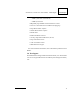
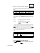
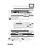
Figure 3.
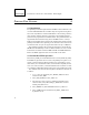
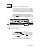
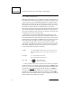
4.3.1.1.3 Handshake with Busy (ACK_OP=0, BUSY_OP=1)
Data transfers are controlled by the use of P_D_STRB (PP_STB) and P_BSY
(PP_BSY). P_ACK (PP_ACK) is a don’t care in this mode. P_BSY
(PP_BSY) is required as an acknowledge after P_D_STRB (PP_STB) and
will gate any further data transfers while it is active. P_BSY (PP_BSY) is also
sampled immediately before P_D_STRB (PP_STB) is generated to ensure
that a data transfer is not attempted while the device is busy. Reference the
data transfer diagram in Figure 4.
Figure 4.
P_DATA (O)
P_D_STRB
(O)
P_ACK (I)
DSS
DSW
1
2
3
4
5
1. Data setup as defined in the hardware configuration register.
2. Data strobe width as defined in the hardware configuration register.
3. Acknowledge is required for each byte transferred.
4. When
P_BSY is active, it gates further data transfers.
5. If
P_BSY is not present, the next data byte will be gated on to the bus following ACK (there is a minimum of three SBus clocks between
the trailing edge of ACK and the next data byte).
6. All signal polarities shown are at the HIOD pins. Polarities on the interface cable should be inverted (except P_DATA).
P_DATA (O)
P_D_STRB
(O)
P_ACK (I)
DSS
DSW
1
2
3
1. Data setup as defined in the hardware configuration register.
2. Data strobe width as defined in the hardware configuration register.
3. Acknowledge is a don’t care condition for all data transfers.
4.
P_BSY is required as an acknowledge for each byte transferred. While P_BSY is present, it gates fuirther data transfers.
5. The next byte of data will be gated on to the bus following the trailing edge of
P_BSY (there is a minimum of three SBus clocks between
the trailing edge of
P_BSY and the next byte of data).
6. All signal polarities shown are at the HIOD pins. Polarities on the interface cable should be inverted (except P_DATA).
Don’t Care
4
5