
Network Router User Manual

24
STP2002QFP
Sun Microelectronics
Fast Ethernet, Parallel Port, SCSI (FEPS) - STP2002QFP
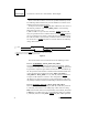
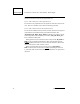
Figure 7.
4.3.1.3.4 Handshake with ACK and BUSY: (BUSY_OP=1, ACK_OP=1)
Both P_ACK (PP_ACK) and P_BSY (PP_BSY) are generated in response to
a data strobe. P_BSY (PP_BSY) will be generated off of the leading edge of
P_D_STRB (PP_STB) and will remain active for 3 SBus clocks beyond the
end of P_ACK (PP_ACK). The position of P_ACK (PP_ACK) relative to the
trailing edge of data strobe is defined by DSS (again DSS has a tolerance of
+3 to 4 SBus clocks). The width of P_ACK (PP_ACK) is set using DSW. The
operation of the interface as defined assumes the bidirectional sense of each
signal has been configured as follows: DIR=1, DS_DSEL=1,
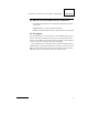
ACK_DSEL=1, BUSY_DSEL=1. Reference the data transfer diagram in
Figure 8.
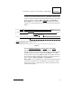
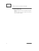
Figure 8.
P_DATA (I)
P_D_STRB
(I)
P_ACK (O)
DSS
1
Logic 0
1. P_BSY hold time after data strobe (DSS - hardware configuration register)
2. All signal polarities shown are at the HIOD pins. Polarities on the interface cable should be inverted (except P_DATA).
P_DATA (I)
P_D_STRB
(I)
P_ACK (O)
DSS
DSW
1
2
3
1. Acknowledge position relative to data strobe (DSS - hardware configuration register).
2. Acknowledge width (DSW - hardware configuration register).
3.
P_BSY is deasserted 3 SBus clocks following the trailing edge of ACK.
4. All signal polarities shown are at the HIOD pins. Polarities on the interface cable should be inverted (except P_DATA).