Sun Blade™ 150 CD-ROM, DVD-ROM, and Hard Drive Installation Guide Sun Microsystems, Inc. 4150 Network Circle Santa Clara, CA 95054 U.S.A. 650-960-1300 Part No. 816-5369-10 June 2002, Revision A Send comments about this document to: docfeedback@sun.
Copyright 2002 Sun Microsystems, Inc., 4150 Network Circle, Santa Clara, California 95054, U.S.A. All rights reserved. Sun Microsystems, Inc. has intellectual property rights relating to technology embodied in the product that is described in this document. In particular, and without limitation, these intellectual property rights may include one or more of the U.S. patents listed at http://www.sun.com/patents and one or more additional patents or pending patent applications in the U.S.
Contents Sun Blade 150 CD-ROM, DVD-ROM, and Hard Drive Installation Required Tools 1 1 Preparing to Replace Components Powering Off the System 2 2 Removing the System Cover 3 Attaching the Antistatic Wrist Strap Removing a Primary Hard Drive 5 Replacing a Primary Hard Drive 7 Installing a Secondary Hard Drive 4 8 Removing a CD-ROM or DVD-ROM Drive 11 Replacing a CD-ROM or DVD-ROM Drive 12 Finishing Component Replacement Powering On the System Hard Drive Mirroring 13 14 14 Hard Drive
Cleaning a CD or DVD 16 Handling and Storing CDs and DVDs iv 16 Sun Blade 150 CD-ROM, DVD-ROM, and Hard Drive Installation Guide • June 2002
Sun Blade 150 CD-ROM, DVD-ROM, and Hard Drive Installation This guide provides instructions for installing a CD-ROM, DVD-ROM, or hard drive in your Sun Blade 150™ system. Required Tools The following tools are required to service the Sun Blade 150 system: ■ No. 2 Phillips screwdriver (magnetized tip suggested) ■ Antistatic wrist strap ■ Antistatic mat Place ESD-sensitive components, such as the hard drives, on an antistatic mat.
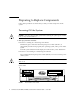
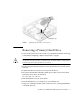
Preparing to Replace Components Follow these procedures to ensure that you safely save data and power off the system. Powering Off the System Caution – Exit from the operating system before turning off system power. Failure to do so may result in data loss. 1. Back up system files and data. ■ If Solaris is running in a windowing environment: Momentarily press and release the front panel power switch (FIGURE 1) to automatically shut down all programs, the operating system, and to power off the system.
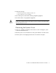
2. Verify the following: ■ The front panel power-indicator LED is off. ■ The system fans are not spinning. 3. Turn off the power to the monitor and any peripheral equipment. 4. Disconnect cables to any peripheral equipment. Caution – Pressing the power switch does not remove all power from the system; a trickle current remains in the power supply. To remove all power from the system, disconnect the power cord. Removing the System Cover 1. Using a No.
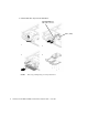
FIGURE 2 Removing the System Cover Attaching the Antistatic Wrist Strap 1. Unwrap the first two folds of the wrist strap. Wrap the adhesive side firmly against your wrist. 2. Peel the liner from the copper foil at the opposite end of the wrist strap. 3. Attach the copper end of the wrist strap to the chassis (FIGURE 3). 4. Disconnect the AC power cord from the system.
Copper end FIGURE 3 Attaching the Wrist Strap to the Chassis Removing a Primary Hard Drive 1. Power off the system, remove the system cover, and attach an antistatic wrist strap as described in “Preparing to Replace Components” on page 2. Caution – Use proper ESD grounding techniques when handling components. Wear an antistatic wrist strap and use an antistatic mat. Store ESD-sensitive components in antistatic bags before placing them on any surface. 2.
8. Lift the hard drive tray from the hard drive.
Replacing a Primary Hard Drive Note – Read the hard drive product guide for information about jumpers, switch settings, or other installation tasks. Note – Before you replace any hard drive, verify that the hard drive mode-select jumper is set to “CS,” “Enable Cable Select,” or “Cable Select.” 1. Position the hard drive into the hard drive tray (FIGURE 4). 2. Turn the tray upside down on an antistatic mat. 3. Using a No.
Installing a Secondary Hard Drive The optional secondary hard drive mounts next to the primary hard drive on the hard drive tray (FIGURE 5). The secondary IDE cable assembly is used with the secondary hard drive. Use the following procedure to install the optional secondary hard drive. 1. Power off the system, remove the system cover, and attach an antistatic wrist strap as described in “Preparing to Replace Components” on page 2. Caution – Use proper ESD grounding techniques when handling components.
CD/DVD-ROM drive IDE cable connector 1 2 IDE 1 (J504) 3 FIGURE 5 4 Secondary hard drive Installing a Secondary Hard Drive 10. Verify that the secondary IDE cable connector is connected to riser board connector IDE2 (J503). See FIGURE 7. Note – Ensure that the cables are properly oriented by aligning the connector keys. 11. Verify that the CD-ROM or DVD-ROM cable is connected to the primary (IDE1, J504) cable connector labeled CD/DVD (FIGURE 5 and FIGURE 6). 12.
J501 J502 FIGURE 6 J504 IDE 1 J503 IDE 2 Riser Board, Side Two 13. Connect the power cable to the secondary hard drive (FIGURE 7). 14. Connect the power cable to the primary hard drive. 15. Connect the secondary hard drive to the cable connector labeled “Secondary HDD”. The following diagram shows the cabling for the secondary hard drive.
16. Detach the wrist strap, replace the system cover, and power on the system as described in “Finishing Component Replacement” on page 13. Removing a CD-ROM or DVD-ROM Drive 1. Remove any CD or DVD media from the drive. 2. Power off the system, remove the system cover, and attach an antistatic wrist strap as described in “Preparing to Replace Components” on page 2. Caution – Use proper ESD grounding techniques when handling components. Wear an antistatic wrist strap and use an antistatic mat.
FIGURE 8 Removing and Replacing a CD-ROM or DVD-ROM Drive Replacing a CD-ROM or DVD-ROM Drive Note – Before you replace the CD-ROM or DVD-ROM drive, verify that the CD-ROM drive jumper (located on the CD-ROM drive back panel) is set to either “CS,” “Cable Select” or “Enable Cable Select.” 1. Position the CD-ROM or DVD-ROM drive in the chassis (FIGURE 8). 2. Push the CD-ROM or DVD-ROM drive toward the chassis rear. 3.
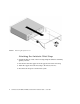
6. Detach the wrist strap, replace the system cover, and power on the system as described in “Finishing Component Replacement” on page 13. Finishing Component Replacement 1. Remove the wrist strap from the system chassis and from your wrist. 2. Position the system cover onto the system chassis. Caution – Ensure that the hard drive cables will not be damaged when you replace the system cover. 3. Slide the system cover toward the front of the system until the cover tabs lock (FIGURE 9). 4. Using a No.
Powering On the System 1. Connect the system power cord to the system and to an AC power outlet. 2. Reconnect and turn on power to any peripherals (so that the system can recognize the peripherals when it is powered on). 3. Press the front panel power switch (FIGURE 10). Power switch FIGURE 10 System Power Switch 4. Verify the following: ■ The front panel power indicator LED is on. ■ The system fans are spinning.
Hard Drive Mirroring Configuration The IDE subsystem of the Sun Blade 150 system has two independent channels designated “primary” and “secondary.” The system riser board has a connector for each IDE Channel, labelled IDE1 (J504) and IDE 2 (J503). Note – When mirroring hard drives in a Sun Blade 150 system, both hard drives should be jumpered as “CS,” “Cable Select” or “Enable Cable Select” to allow for automatic configuration. Two IDE cables are required for this configuration.
2. Place the CD (label side up) into the tray. Ensure that the CD is properly set into the recessed area of the tray. 3. Push the tray to close it. Ejecting a CD or DVD You may need to unmount the CD before manually ejecting it. There are three ways to eject a CD: ■ Press the eject button on the front of the CD-ROM drive. ■ Use software commands to eject the CD. Refer to the peripherals handbook that corresponds with your operating system.